background image

ST-85 – USER'S MANUAL

Table of Contents

I.  Description.......................................................................................5
II. Regulator Functionality......................................................................8

II.a) Main Page..................................................................................8
II.b) Changing the central heating and hot consumption water setpoint 
temperature...................................................................................... 9
II.c) Firing up.................................................................................... 9
II.d) Manual Mode............................................................................10
II.e) Fuel Type.................................................................................11
II.f) Central Heating Pump Activation..................................................11
II.g) H.C.W. Pump  Activation............................................................11
II.h) Operation Mode.........................................................................12

II.h.1) House Heating.....................................................................12
II.h.2) H.C.W. Priority....................................................................12
II.h.3) Parallel Pumps.....................................................................13
II.h.4) Summer Mode.....................................................................13

II.i) Main Screen...............................................................................14
II.j) Language..................................................................................15
II.k) Factory Settings........................................................................15
II.l) Fitting parameters......................................................................15

III. Protections....................................................................................16

III.a) Thermal protection...................................................................16
III.b) Automatic Sensor Check............................................................16
III.c) Temperature Protection.............................................................17
III.d) Anti-Boil Protection...................................................................17
III.e) Monitoring the flue gas outlet temperature..................................18
III.f) Fuse........................................................................................ 18

IV. Maintenance..................................................................................18
V. Assembly........................................................................................19

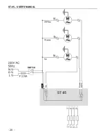
V.a) Cable Connection Diagram for Controller.......................................20

- 22 -

Summary of Contents for ST-85

Page 1: ......

Page 2: ...mpliant with the Regulation by the Ministry of Economy Journal of Laws Dz U 155 Item 1089 of July 21 2007 implementing provisions of the Low Voltage Directive LVD 2006 95 EC of January 16 2007 The ST...

Page 3: ...from the mains before working on the power supply cable connections device installation etc All connection works must only be carried out by qualified electricians Before activating the controller mea...

Page 4: ...Blow...

Page 5: ...and its power depends directly on the measured boiler temperature and flue gas temperature as well as the difference between the two parameters and their setpoint values Advantages of zPID regulators...

Page 6: ...sults presented below were obtained using the Tech PID based controller and the controller without PID control You can change all parameters with an encoder knob Turning the knob allows you to select...

Page 7: ...The duty cycle is the basic functionality of the regulator The blow is controlled automatically using the zPID algorithm and the temperature is close to its setpoint value In the user menu fan item wi...

Page 8: ...user II a Main Page During normal operation the LCD display shows the Main Page containing the following Boiler temperature to the left of the display Setpoint temperature to the right of the display...

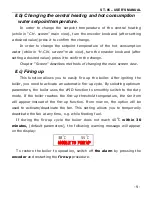
Page 9: ...to easily fire up the boiler After igniting the boiler you need to activate an automatic fire up cycle By selecting optimum parameters the boiler uses the zPID function to smoothly switch to the duty...

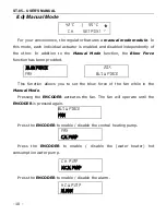
Page 10: ...ction allows you to set the blow force of the fan while in the Manual Mode Pressing the ENCODER activates the fan The fan will operate until the ENCODER is pressed again Press the ENCODER to enable di...

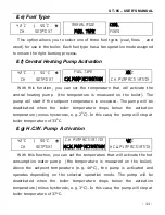
Page 11: ...this case the pump will stop at boiler temperature of 33O C II g H C W Pump Activation With this function you can set the temperature that will activate the hot consumption water pump the temperature...

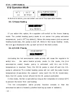
Page 12: ...o switch into the water heater priority mode In this mode the hot consumption water heater pump is activated until the set H C W temperature is reached Then the H C W pump is shut off and the C H pump...

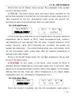
Page 13: ...esholds are exceeded the pumps will operate simultaneously The central heating pump runs continuously while the hot consumption water pump stops after the setpoint temperature is reached in the water...

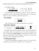
Page 14: ...heater While in the Summer Mode the icon is displayed in the up right corner of the main screen II i Main Screen This function allows you to change the view of the main screen The following views are...

Page 15: ...re configured However it should be adjusted to your individual needs It is possible to return to the factory settings at any time By enabling the Factory Settings all existing boiler settings will be...

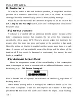
Page 16: ...em when the boiler has been overheated or the controller is damaged When the protective function is enabled and the temperature drops to a safe value the sensor will automatically restart the device a...

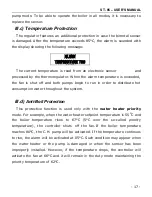
Page 17: ...hroughout the system III d Anti Boil Protection This protective function is used only with the water heater priority mode For example when the water heater setpoint temperature is 55O C and the boiler...

Page 18: ...is operated using only the boiler sensor and the zPID function remains active without the flue gas outlet sensor III f Fuse The regulator has a network protection WT 3 15 A tube fuse Higher current r...

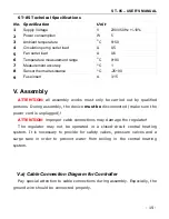
Page 19: ...orks must only be carried out by qualified persons During assembly the device must be disconnected make sure the power cord is unplugged ATTENTION improper cable connections may damage the regulator T...

Page 20: ...ST 85 USER S MANUAL 20...

Page 21: ...ces Hence we have been entered into a register kept by the Inspection For Environmental Protection The crossed out bin symbol on a product means that the product may not be disposed of to household wa...

Page 22: ...on 11 II h Operation Mode 12 II h 1 House Heating 12 II h 2 H C W Priority 12 II h 3 Parallel Pumps 13 II h 4 Summer Mode 13 II i Main Screen 14 II j Language 15 II k Factory Settings 15 II l Fitting...

Page 23: ...ST 85 USER S MANUAL 23...

Page 24: ...ST 85 USER S MANUAL 24...

Reviews: