TM Palletizing Operator User’s Manual
Product Version: 1.1 Document Version: 1.2
68
Analog Pin Symbols:
AOUT_V = Analog Output_Voltage
AOUT_G = Analog
Output_Ground
AIN_xP = Analog Input_xPositive
AIN-xG = Analog Input_xGround
REMO+/- = Reserved
Range
Resolution
Accuracy
Conversion Time
Analog Input
-10.00V ~ +10.00V
11bit
≤ 0.2%
1 ms
Analog Output
-10.00V ~ +10.00V
11bit
± 0.07%
1 ms
Analog Input
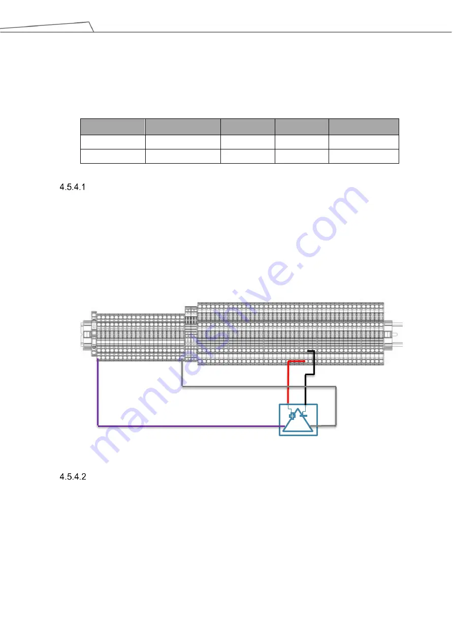
Analog Input only supports a certain voltage mode and the detectable range is between -
10.00V and +10.00V.
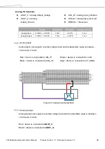
Red = device is connected to AIN_1P
Purple = device is connected to +24V
Black = device is connected to AIN_1G
Gray = device is connected to 0V (GND)
Figure 23: Analog Input Application
Analog Output
Analog Output only supports a certain voltage mode and the detectable range is between -
10.00V and +10.00V.
Red = device is connected to
AOUT_V
Black = device is connected to
AOUT_G
Summary of Contents for TM Palletizing Operator
Page 40: ...TM Palletizing Operator User s Manual Product Version 1 1 Document Version 1 2 40 ...
Page 182: ...TM Palletizing Operator User s Manual Product Version 1 1 Document Version 1 2 182 ...
Page 183: ...TM Palletizing Operator User s Manual Product Version 1 1 Document Version 1 2 183 ...
Page 185: ...TM Palletizing Operator User s Manual Product Version 1 1 Document Version 1 2 185 ...


