TM Palletizing Operator User’s Manual
Product Version: 1.1 Document Version: 1.2
72
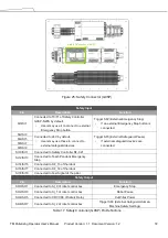
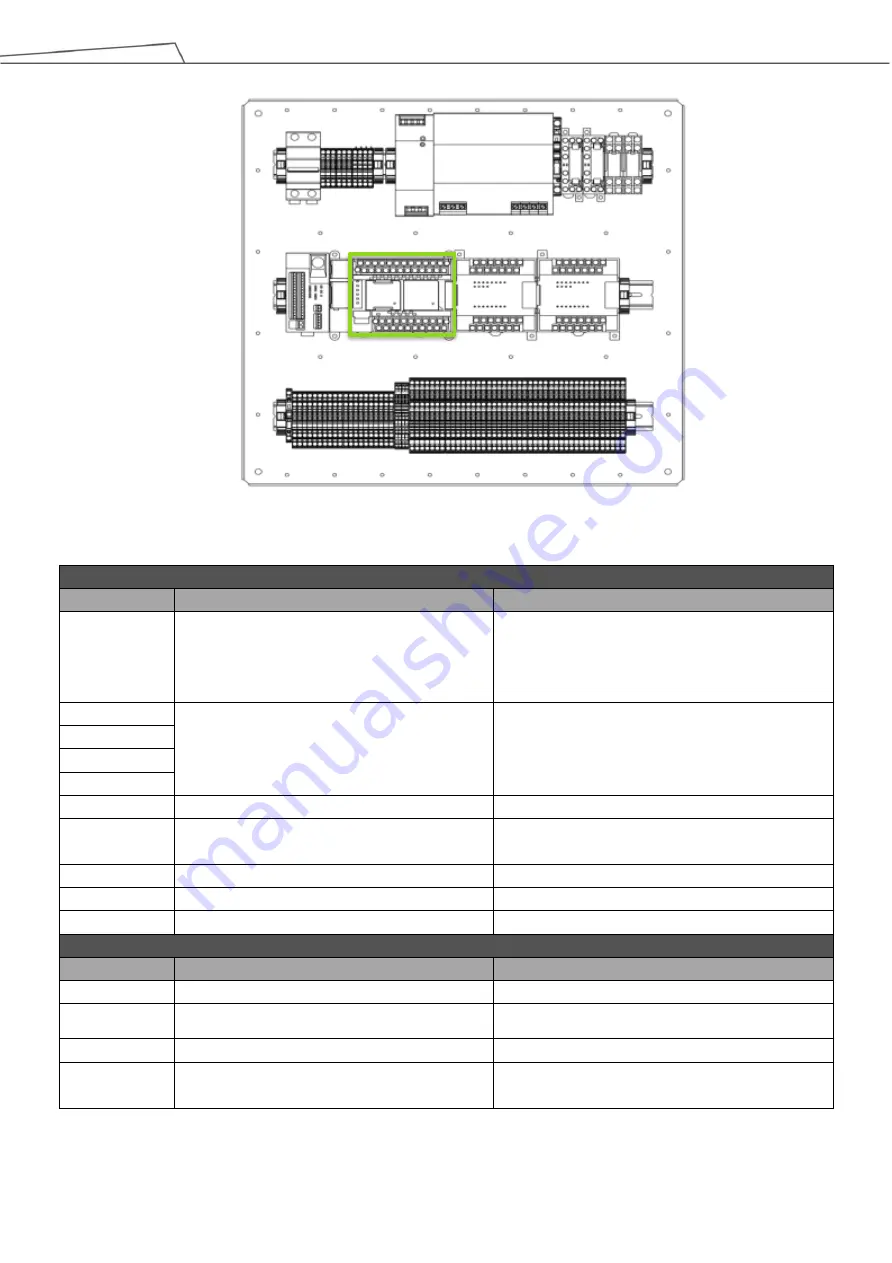
Figure 25: Safety Connector (G9SP)
Table 17: Safety Controller (G9SP) Pin Definitions
Safety Input
Pin
Description
Function
SI0/SI1
Connected to T0/T1 of Safety Controller
G9SP-N20S by default.
•
Users may use it to connect to external
Emergency Stop button.
Trigger SF2 (External Emergency Stop)
•
If an external Emergency Stop button is
connected.
SI2/SI3
Connected to 24V by default.
•
Users may use these to connect to
external safeguard devices.
Trigger SF3 (External Safeguard-Pause)
•
If external safeguard devices are
connected.
SI4/SI5
SI6/SI7
SI8/SI9
SI10/SI11
Connected to Safety Controller SF-C21
SI12/SI13
Connected to Teach Pendant Emergency
Stop
SI14/SI15
Connected to SF_13 of the robot
SI16/SI17
Connected to SF_14 of the robot
SI18/SI19
Connected to Test Signal of the pillar
Safety Output
Pin
Description
Function
SO0/SO1
Connected to SI_0 of robot control box
Emergency Stop
SO2/SO3
Connected to SI_1 of robot control box
Robot Pause
SO4/SO5
Connected to CR1/CR3 of Safety Relay
Cut Pillar Power
SO6/SO7
Connected to SI_2 of robot control box
Trigger SF4 (External Safeguard-Human-
Machine Safety Settings)
Safety Connector (G9SP)
Summary of Contents for TM Palletizing Operator
Page 40: ...TM Palletizing Operator User s Manual Product Version 1 1 Document Version 1 2 40 ...
Page 182: ...TM Palletizing Operator User s Manual Product Version 1 1 Document Version 1 2 182 ...
Page 183: ...TM Palletizing Operator User s Manual Product Version 1 1 Document Version 1 2 183 ...
Page 185: ...TM Palletizing Operator User s Manual Product Version 1 1 Document Version 1 2 185 ...


