- 21 -
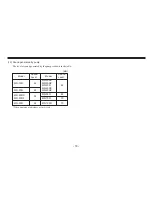
10-3. Wiring
(1)
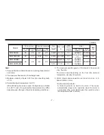
Prior to wiring work, check the voltage specified on the name-
plate.
Use specified wiring materials. (Observe the local regulations
related with electrical work.) The connection diagram and the
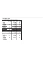
table showing the rated current and starting current for each
model are presented below.
(2)
Do not fail to connect a ground wire (green/yellow).
(3)
The pump has no On/Off switch. It starts operation when power is
supplied by connecting the power supply cable or other means.
■
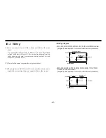
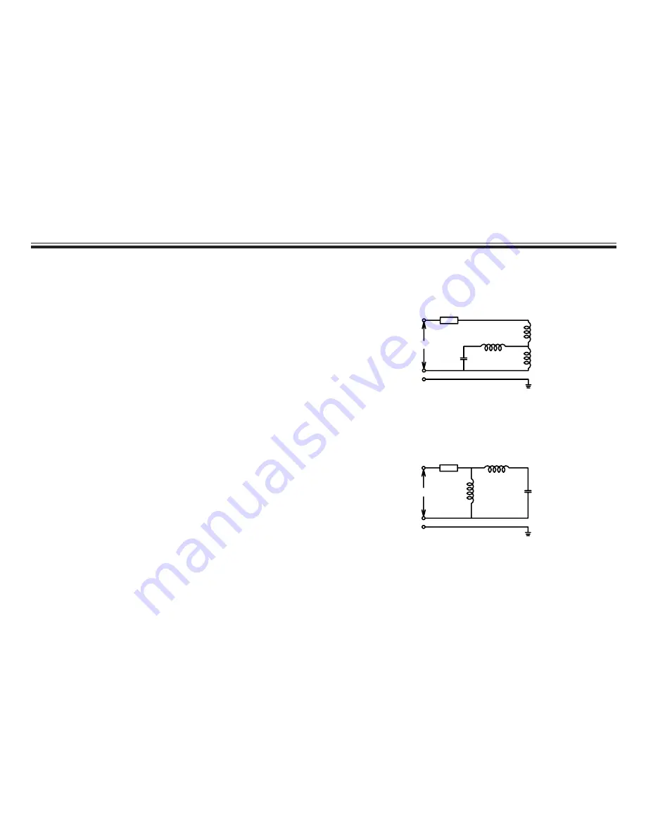
Wiring diagram
• MD-15R, 20R, 20RX, 20RZ, 30R, 30RX and 30RZ models
(Single-phase capacitor run motor with thermal protector)
Brown
Blue
Yellow/Green
Thermal protector
Power source
Auxiliary coil
Capacitor
Main coil
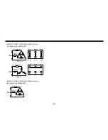
• MD-40R, 40RX, 40RZ, 40RZ-5, 55R, 55R-5, 70R, 70RZ,
100R and 100R-5 models
(Single-phase capacitor run motor with thermal protector)
Brown
Blue
Yellow/Green
Thermal protector
Power source
Auxiliary coil
Capacitor
Main coil
Summary of Contents for FSSR1
Page 1: ...Issue 1 02 07 FSSR1 Venturi Scrubber Unit OPERATOR S MANUAL ...
Page 7: ...1 Appendix 1 Scrubber Layout ...
Page 8: ...A3 ...
Page 9: ...Appendix 2 Operating and Maintenance Instructions for Pump ...
Page 10: ...Read this manual before use of product MD SERIES Instruction Manual IWAKI Magnetic Drive Pump ...

