TEP-0500-IMX7 HARDWARE MANUAL
– VER 1.00 – AUG 03 2018
Page
15
of
27
GPIO2:
Pin
#
Signal
Description
Voltage
Current
Max.
PWM
(default)
GPIO*
Kernel
GPIO
Bank/IO
Min.
Typ.
Max.
1
GPIO2A
ADCI_INO
-0.3V
3.3V
2
GPIO2B
PWM_OUT or
DIG_IN2/OUT2
-0.3V
3.3V
3.6V
0.66mA
1
8
1_8
3
GND_DIO
Ground for digital
I/O
4
NC
5
GPIO2C
PWM_OUT or
DIG_IN5/OUT5
-0.3V
3.3V
3.6V
0.66mA
2
9
1_9
6
GPIO2D
PWM_OUT or
DIG_IN6/OUT6
-0.3V
3.3V
3.6V
0.66mA
4
11
1_11
7
VCC_DIO
Supply output
3.3V
8
NC
NOTE: GPIO2 port is set by default as PWM. GPIO setting requires software modification. Please
connect with TechNexion support team for more details.
Header on TEP-0500-IMX7: Molex 43045-0812 (8-pin Micro-Fit 3.0).
Cable receptacle: Molex 43025-0800 (8-pin Micro-Fit 3.0) plug with crimp contact Molex 43030-0007.
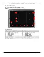
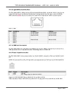
3.4. S1 Button
The TEP-0500-IMX7
by default boots the unit from internal flash storage (eMMC). By pressing the “S1”
button before applying power to the unit and keeping the button pressed for 10 seconds, the unit will boot
from an alternative boot media (microSD card).
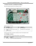
3.5. RST Button
The TEP-0500-IMX7
features a “RST” button for system reset.
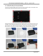
3.6. LED Light Indicator
The TEP-0500-IMX7 has one programmable LED Light indicator.
LED #
Color
GPIO Kernel
GPIO Bank/IO
1
Green
179
6_19


