TEP-0500-IMX7 HARDWARE MANUAL
– VER 1.00 – AUG 03 2018
Page
16
of
27
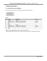
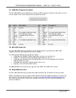
3.7. USB OTG (Type-C) Connector
The TEP-0500-IMX7 has one USB Type-C connector (USB 2.0 signals only) that can be used to connect
a host computer to the unit for programming and update purposes.
Pin
#
Signal
Description
Pin
#
Signal
Description
A1
GND
Ground
B1
GND
Ground
A2
NC
B2
NC
A3
NC
B3
NC
A4
VBUS
5V Universal Serial Bus Power
B4
VBUSD
5V Universal Serial Bus Power
A5
CC1
OTG detection signal
B5
CC2D
OTG detection signal
A6
USB_D+ USB differential pair signal
port 1
B6
USB_D+ USB differential pair signal
port 2
A7
USB_D-
B7
USB_D-
A8
NC
B8
NC
A9
VBUS
5V Universal Serial Bus Power
B9
VBUSD
5V Universal Serial Bus Power
A10
NC
B10
NC
A11
NC
B11
NC
A12
GND
Ground
B12
GND
Ground
3.8. MicroSD Connector
The TEP-0500-IMX7 features a standard microSD cardslot which is connected to the NXP i.MX7
integrated “Ultra Secured Digital Host Controller” (uSDHC).
The following main features are supported by uSDHC:
•
Compatible with the MMC System Specification version 4.2/4.3/4.4/4.41/5.0.
•
Conforms to the SD Host Controller Standard Specification version 3.0.
•
Compatible with the SD Memory Card Specification version 3.0 and supports the “Extended
Capacity SD Memory Card”.
•
Compatible with the SDIO Card Specification version 3.0.
•
Supports 1-bit / 4-bit SD and SDIO modes
The MMC/SD/SDIO host controller can support a single MMC / SD / SDIO card or device.
3.9. Nano-SIM Connector
The TEP-0500-IMX7 features an external Nano-SIM cardslot for use by 3G/4G/LTE wireless module.
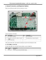
NOTE: This cardslot can be only used by a M.2 3G/4G/LTE module installed into the M.2 connector. The
M.2 connector can be found at location “B” in chapter
4. Internal Connectors and Expansion Options
of
this manual. No M.2 3G/4G LTE module is included in this device (must be purchased separately, not
sold by TechNexion).

