TEP-0700-IMX7 HARDWARE MANUAL
– VER 1.00 – MAR 11 2019
Page
20
of
26
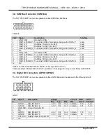
Header on TEP-0700-IMX7: Molex 53047-0210 (1.25mm Pitch PicoBlade Wire-to-Board Header).
Cable receptacle: Molex 051021-8602 (1.25mm Pitch PicoBlade Wire-to-Wire and Wire-to-Board Housing)
plug with crimp contact Molex 50058-8000.
Battery P/N: KTS BCR2032H14.0AM1XB.
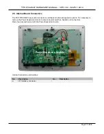
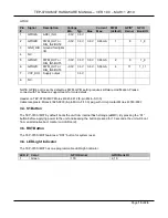
4.2. M.2 KEY-B 3G/4G LTE Module Connector
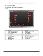
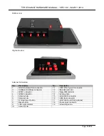
The TEP-0700-IMX7 has an internal M.2 KEY-B 3G/4G LTE module (USB 2.0 signals) connector (Marked
B). M.2 cards in the industry-standard M.2 KEY-B 3042 (30 x 42 mm) or M.2 KEY-B 2242 (22 x 42 mm)
form factor are supported.
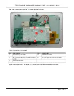
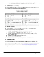
4.3. SW3 Panel Backlight Switch
The TEP-0700-IMX7 has an internal SW3 Panel Backlight switch (Marked C). Always use the default
settings.
Pin #
5” Panel
7” Panel (default)
1-2
OFF
ON
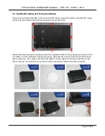
4.4. SW2 Panel Scanning Direction Switch
The TEP-0700-IMX7 has an internal SW2 Panel Scanning Direction switch (Marked D). Always use the
default settings.
Pin #
5” Panel
7” Panel (default)
Description
1-8
ON
OFF
Down to Up
2-7
OFF
OFF
Up do Down
3-6
OFF
OFF
Left to Right
4-5
OFF
OFF
Right to Left

