GB
12
•
Operating mode selection
:
- the controller is factory configured to control the unit by 3 outside contacts:
• On / Stand-by ,
• Heating / Cooling.
- in stand-by mode, the circulating pump continues to function.
Note:
It is possible to shut the unit down completely (circulating pump stopped) by pressing the
ON/OFF
button (1).
- this configuration is adapted to system applications,
- for other applications, the following configurations are possible by modifying the parameterization:
a) Complete shut-down ("
OFF
") by remote contact (instead of "
stand-by
").
In the "
CnF
" configuration section, change the parameter
H20
from
7
(remote stand-by) to
4
(remote
OFF
). In the
case of r
emove
"
OFF
" complete shut-down, the display is off. Only the decimal indicator
lamp flashes
.
b) Selection of the heating / cooling mode using the display unit's keys.
In the "
CnF
" configuration section, change the parameter
H27
from
1
(selection by remote contact) to
0
(selection by
keypad).
This configuration is chosen in the case where the remote display unit
70250055
is used (Accessory, see installation
in paragraph 6.3) to control the unit, for example.
The operating mode is thus selected by successively pressing the "mode" button (2) according to the following
sequence:
---> stand-by ---> cooling ---> heating ---> stand-by ---
The stand-by mode is indicated by the extinction of the heating and cooling mode indicator lamps.
•
Pre-ventilation
:
- generally speaking, in order to condition the air heat exchanger, the fan always starts at full speed a few seconds before
the compressor.
•
Anti short-cycle time delays
:
- the compressor control features a time delay system in order to respect:
• a maximum number of starts per hour (12),
• a minimum stop time (150 seconds).
•
Cycle inversion valve
:
- The valve is actuated in heating mode.
•
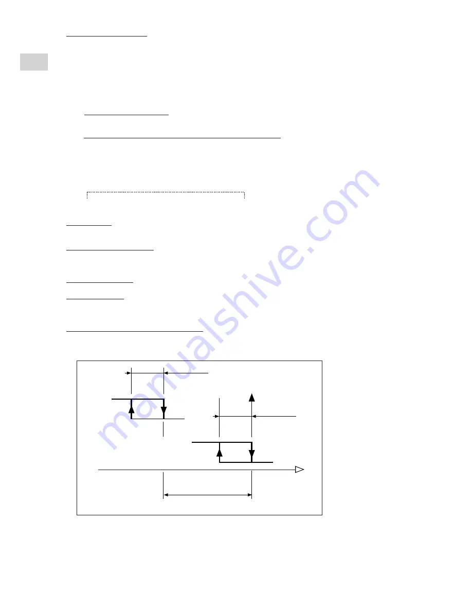
Control hysteresis:
- See the operating diagrams in paragraph 5.4,
- The hysteresis in both heating and cooling modes are factory set at 2k. They can be modified. To do this, change
parameters
C03
(cooling hysteresis) and/or
C04
(heating hysteresis) in the compressor section "
CP
".
•
Supplementary heating authorisation, if any
:
- potential-free, normally-open contact (2A resistive - 250 VAC maxi.) available on the unit's terminal strip (terminals 10
and 11),
- for authorisation of supplementary heating, if any, other than that on the buffer tank.
0
1
1
0
Heating hysteresis
Heating hysteresis
Heating set point
Water temperature
Supplementary
heating
Compressor
Differential between stages
Parameter r14
is factory set at 5k
- the supplementary heating control is authorized only if the unit's control unit is actuated in heating mode and provide
there is no water output or probe alarm.


