GB
17
6.5.4 - ELECTRICAL CONNECTIONS: model with supplementary heating
See the general information about the electrical connections in § 4.2.1.
•
CAUTION: in the case where the tank and the unit are mounted separately, make sure that the grounds of both
equipment are interconnected
.
•
Note
: The control connections with the unit are not supplied.
• Electrical diagram No.
1005753
.
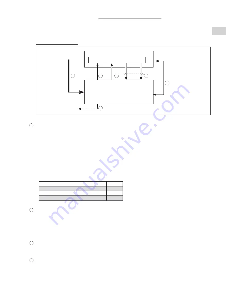
Description of connections:
E
B
A
F
C
D
AUXILIARY HEATING POWER SUPPLY
•
The power supply (three-phase 400 V) is separate from the unit and is connected directly on the power switch
of the heating control unit
.
• The power supply must come from an isolation and electric protection device (not supplied) in accordance with existing
regulations.
• The sizing of the power supply cables is to be ensured by the installer in accordance with the installation conditions and
as per current standards.
Cable sizes, indicated below, are given for information purposes.
They are calculated in accordance with NFC 15-100 (
≈
CEI 364) with the following hypotheses:
- Maximum current, see table below.
- Multi-pole copper cable with PR insulation.
- Installation in non-ventilated cable duct (installation method No. 41). No other power cable.
- Ambient temperature 40°C.
• The lengths indicated below correspond to a voltage drop less than 5% in the cable.
GROUP CONTROL
• Use shielded cable with 2 twisted pairs (shielding grounded on generator side):
- 1 pair for unit operator,
- 1 pair for Heating / Cooling changeover.
• Maximum cable length: 100 meters.
• Min. cable size: 0.5 mm
2
.
To avoid problems related to electromagnetic disturbances, this cable must not be routed near power cables.
CIRCULATING PUMP CONTROL
• 2-conductor cable adapted to the 230 Vac of the unit's control circuit.
• Min. cable size: 0.75 mm
2
.
HEATING AUTHORISATION
• 4-conductor cable adapted to the 230 Vac of the supplementary heating control circuit.
• Min. cable size: 0.75 mm
2
.
A
Heating power
kW
24
Max. current
A
35
Power supply cable
mm
2
10
Max. connection length
m
150
B
C
D
UNIT
Electrical box
heating power
supply
400 V / 3 Ph / 50 Hz
Supplementary
heating alarm report
(as required)
Water temperature
sensor (*)
(installation return)
TANK
Supplementary heating control,
electrical box
Group
control
Pump
control
Supplementary
heating
authorization
3
rd
back-up
stage
authorization
(*) Sensor delivered in the heating
control unit


