12
The second part of the connection is the RJ-45 cable from the modem to the CPE, which can be any Ethernet
connected device.
3
3
3
.
.
.
3
3
3
.
.
.
2
2
2
I
I
I
n
n
n
s
s
s
t
t
t
a
a
a
l
l
l
l
l
l
a
a
a
t
t
t
i
i
i
o
o
o
n
n
n
o
o
o
f
f
f
a
a
a
P
P
P
O
O
O
T
T
T
S
S
S
s
s
s
p
p
p
l
l
l
i
i
i
t
t
t
t
t
t
e
e
e
r
r
r
POTS-splitters prevent high frequency energy from reaching the POTS device and to provide isolation from impedance
effects of the PORTS device on DSL. As the splitter is installed at the demarcation point, only 1 splitter is required for all
devices.
A POTS splitter has to be installed directly connected to the wall-socket, at the location where the phone line enters
the building, or at least between all devices and the demarcation to the telephone carrier.
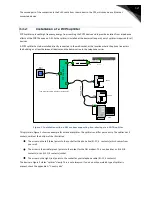
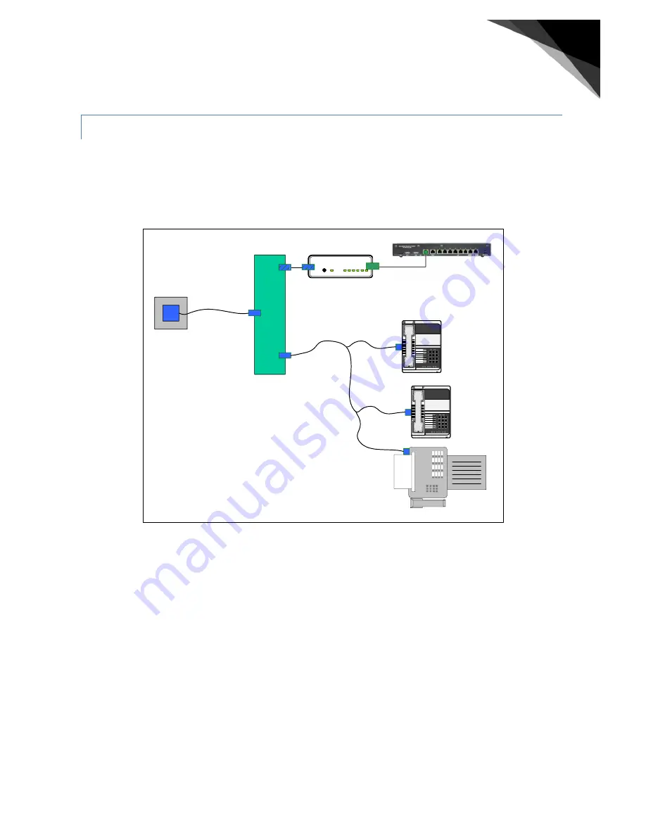
Figure 3 Installation with a xDSL modem supporting line-sharing via a POTS-splitter
This picture in Figure 3 shows an example for a standard splitter. The splitter can differ per country. The splitter has 3
sockets, visible at the bottom of the illustration:
•
The arrow on the left (blue) points to the socket for the phone line (RJ-11, 4 contacts), which comes from
your wall.
•
The arrow in the middle (green) points to the socket for the DSL modem. This can be either an RJ-45 (8
contacts) or an RJ-11 (4 contacts) socket.
•
The arrow on the right (red) points to the socket for your telephone cable (RJ-11, 4 contacts).
The device in Figure 2 states “splitter” clearly. This is not always so. If you do not know which type of splitter is
present, check the appendix A: “Country kits”.
RS CS TR RD TD CD
TALK / DATA
TALK
RJ-
11
Wall
socket
P
O
TS
-s
p
lit
te
r
RJ-45
1 2 3
4 5 6
7 8 9
*
8 #
xDSL-modem/Router
1 2 3
4 5 6
7 8 9
*
8 #
RJ-11
or RJ-45
* Can differ to comply with country standards
RJ-11*
RJ-11*
RJ-11*
RJ-11*
RJ-11*
Phone
FAX
Phone
In
-h
o
u
se
w
ir
in
g
Ethernet cable
RJ-45


