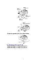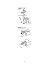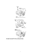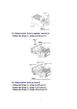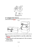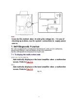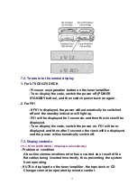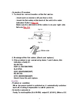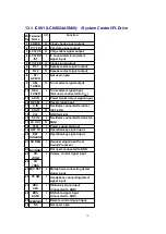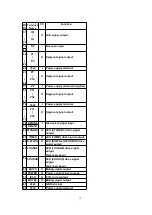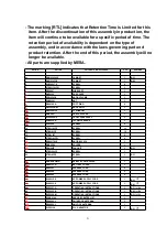
voltage is applied to speaker terminals.)
8. Type Illustration of ICs, Transistors and Diodes
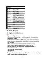
9. Schematic Diagram Notes
- This schematic diagram may be modified at any time with the
development of new technology.
Notes:
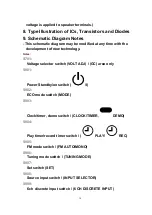
S701:
Voltage selector switch (VOLT ADJ) / (GC) area only
S901:
Power Standby/on switch (
/I)
S902:
ECO mode switch (MODE)
S903:
Clock/timer, demo switch / (CLOCK/TIMER,
DEMO)
S904:
Play timer/record timer switch / (
PLAY/
REC)
S905:
FM mode switch / (FM AUTO/MONO)
S906:
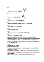
Tuning mode switch / (TUNING MODE)
S907:
Set switch (SET)
S908:
Source input switch / (INPUT SELECTOR)
S909:
6 ch discrete input switch / (6 CH DISCRETE INPUT)
14
Summary of Contents for RS-EH760
Page 7: ...7 ...
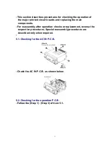
Page 8: ... Check the main P C B as shown below 8 ...
Page 30: ...R944 ERDS2FJ222 1 4W 2 2K 1 30 ...
Page 32: ...16 Cabinet Parts Location 17 Packaging 32 ...
Page 33: ...F000400000YM KH 33 ...


