17
7.2.
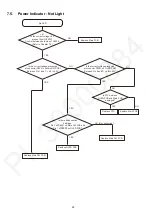
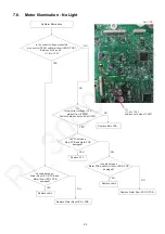
No power
Repl
a
ce the
A
C
ma
ins le
a
d.
NO
<1>
Is the
A
C po
w
er presented
a
t
A
C inlet (P1001)?
Repl
a
ce
S
MP
S
PCB.
NO
<
2
>
Is
f
use F1001, F1101
or F1
6
01 o
ka
y?
Repl
a
ce
S
MP
S
PCB.
NO
<3>
Is the correct volt
ag
e presented
a
t the connector
P1501?
No po
w
er
S
MP
S
PCB
Y
E
S
Y
E
S
p
<1>
A
C inlet (P1001)
<
2
> FU
S
E F1001
<3> Connector P1501 (to
A
MP PCB)
Y
E
S
Go to next p
ag
e.
1) Po
w
er OFF/Burst
m
ode
Pin
2
3 : PW_48R0
V
= 0
V
Pin 1
7
-
22
: PW_4
2
R0
V
= 30 to
40
V
Pin 8 : Burst_
S
W = +3.3
V
Pin 4 - 5 : PW_14R0
V
= 10 to 1
2V
2
) Po
w
er ON
Pin
2
3 : PW_48R0
V
= 48 to 5
2V
Pin 1
7
-
22
: PW_4
2
R0
V
= 4
2
to 4
7V
Pin 8 : Burst_
S
W = 0
V
Pin 4 - 5 : PW_14R0
V
= 14 to 15
V
<
2
> FU
S
E F1101
<
2
> FU
S
E F1
6
01
1
S
MP
S
_REGION
2
GND
3
GND
4
PW_14R0
V
5
PW_14R0
V
6
A
C_
SY
NC
7
TH-DET
8
BUR
S
T_
S
W
9
P_CONT
10
PGNG
11
PGNG
1
2
PGNG
13
PGNG
14
PGNG
15
PGNG
1
6
PGNG
1
7
PW_4
2
R0
V
18
PW_4
2
R0
V
19
PW_4
2
R0
V
2
0
PW_4
2
R0
V
2
1
PW_4
2
R0
V
22
PW_4
2
R0
V
2
3
PW_48R0
V
Con
f
ir
m
v
a
lue o
f
resistor
bet
w
een Ju
m
per W3
6
a
nd
Pin 4 o
f
Connector P1501.


