background image

2

7.17. No Audio Output from PRE OUT terminal --------- 34
7.18. No LAPC Function --------------------------------------- 34
7.19. Pin function of each connectors ---------------------- 35
7.20. Function and Possible failure PCB or Module ---- 36

8 Disassembly and Assembly Instructions --------------- 37

8.1. Type of Screws ------------------------------------------- 37
8.2. Disassembly Flow Chart-------------------------------- 38
8.3. Main Components and P.C.B. Locations ----------- 39
8.4. Disassembly of Top Cabinet Ass’y------------------- 40
8.5. Disassembly of SMPS P.C.B.  ------------------------ 40
8.6. Disassembly of AMP P.C.B.  -------------------------- 41
8.7. Disassembly of Speaker L P.C.B. and Speaker

R P.C.B. ---------------------------------------------------- 42

8.8. Disassembly of Control P.C.B.  ----------------------- 42
8.9. Disassembly of Digital P.C.B.  ------------------------ 43

8.10. Disassembly of REC Out P.C.B. --------------------- 43

8.11. Disassembly of Main P.C.B.  -------------------------- 44

8.12. Disassembly of Front Panel Unit --------------------- 44
8.13. Disassembly of Selector P.C.B.----------------------- 45
8.14. Disassembly of Volume P.C.B.------------------------ 45
8.15. Disassembly of Main SW P.C.B. --------------------- 46
8.16. Disassembly of OLED P.C.B. ------------------------- 46
8.17. Disassembly of Shade Sheet B ---------------------- 46
8.18. Disassembly of Headphone P.C.B. ------------------ 46
8.19. Disassembly of Meter Illumi LED L P.C.B. and

Meter Illumi LED R P.C.B.------------------------------ 47

8.20. Disassembly of Meter P.C.B. -------------------------- 47
8.21. Disassembly of Meter Unit ----------------------------- 47

9 Service Position ------------------------------------------------- 48

9.1. Checking and Repairing of SMPS P.C.B.,

AMP P.C.B., Main P.C.B., Control P.C.B.,
Digital P.C.B. and REC Out P.C.B.  ------------------ 48

10 Measurement and Adjustment------------------------------ 49

10.1. Adjustment of the Peak Power Meter --------------- 49

11 Block Diagram --------------------------------------------------- 51

12 Wiring Connection Diagram --------------------------------- 52
13 Exploded View and Replacement Parts List ----------- 53

13.1. Cabinet Parts Location 1 ------------------------------- 53
13.2. Cabinet Parts Location 2 ------------------------------- 54
13.3. Cabinet Parts Location 3 ------------------------------- 55
13.4. Packaging -------------------------------------------------- 56
13.5. Mechanical Replacement Part List ------------------ 57
13.6. Electrical Replacement Parts List -------------------- 59

Summary of Contents for SU-G700E

Page 1: ...ce Information 8 4 Specifications 9 5 Location of Controls and Components 10 5 1 Remote Control Key Button Operation 10 5 2 Main Unit Key Button Operation 11 6 Service Mode 12 6 1 Doctor Mode 12 6 2 E...

Page 2: ...bly of Selector P C B 45 8 14 Disassembly of Volume P C B 45 8 15 Disassembly of Main SW P C B 46 8 16 Disassembly of OLED P C B 46 8 17 Disassembly of Shade Sheet B 46 8 18 Disassembly of Headphone P...

Page 3: ...is evident 4 After servicing be sure to restore the lead dress insulation barriers insulation papers shields etc 5 Before returning the serviced equipment to the customer be sure to make the followin...

Page 4: ...on DO NOT SHORT CIRCUIT DIRECTLY with a screwdriver blade for instance as this may destroy solid state devices After repairs are completed restore power gradually using a variac to avoid overcurrent C...

Page 5: ...e power is first turned off and then on again 1 4 Safety Parts Information Safety Parts List There are special components used in this equipment which are important for safety These parts are marked b...

Page 6: ...rotective material from the leads of a replacement ES device touch the protective material to the chassis or circuit assembly into which the device will be installed CAUTION Be sure no power is applie...

Page 7: ...6 5 silver Ag 3 0 Copper Cu 0 5 Cobalt Co Germanium Ge 0 1 to 0 3 2 3 Grounding for electrostatic breakdown prevention As for parts that use optical pick up laser diode the optical pick up is destroye...

Page 8: ...odel Please place orders using the parts list and not the drawing reference numbers If the circuit is changed or modified this information will be followed by supplement service manual to be filed wit...

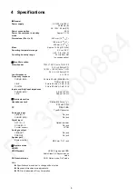
Page 9: ...AA DEVIA TION 1 dB 8 LINE 5 Hz to 80 kHz 3 dB 8 DIGITAL 5 Hz to 90 kHz 3 dB 8 Input sensitivity Input impedance PHONO MM 2 5 mV 47 k LINE 200 mV 22 k Q Terminals section Headphones Jack Stereo 6 3 mm...

Page 10: ...10 5 Location of Controls and Components 5 1 Remote Control Key Button Operation...

Page 11: ...11 5 2 Main Unit Key Button Operation...

Page 12: ...n remote control To exit power off on remote control To exit power off on remote control To exit power off on remote control To exit power off on remote control 001 0001 means each version number Sele...

Page 13: ...aintain Doctor Mode Dimmer Check To change the level of brightness You can change the level of brightness by pressing the DIMMER on remote This spec is same as normal mode Standard Dimmer level 1 Dimm...

Page 14: ...e SU G700 to ST C700D ST C700 with Control cable When press NWP key on remote control it starts communicate with SU G700 and ST C700D ST C700 for System Combination function NWP Tx Send the command to...

Page 15: ...in Log F70 DAP Output in Log F70 USB DAC Output in Log F70 EEPROM Output in Log F78 VirtualBatt To exit power off on remote control To exit power off on remote control To exit power off on remote cont...

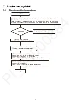
Page 16: ...is reproduced Approx 3 minutes are required to discharge electricity from the electrolytic capacitors at the power source Always wait for 3 minutes after power off when checking other items as well T...

Page 17: ...Burst mode Pin 23 PW_48R0V 0V Pin 17 22 PW_42R0V 30 to 40V Pin 8 Burst_SW 3 3V Pin 4 5 PW_14R0V 10 to 12V 2 Power ON Pin 23 PW_48R0V 48 to 52V Pin 17 22 PW_42R0V 42 to 47V Pin 8 Burst_SW 0V Pin 4 5 PW...

Page 18: ...AC mains lead to the wall outlet 3 3 V is output in both power on and off condition If no 3 3V is output main microcomputer won t function Disconnect FFC between Main PCB and OLED PCB Is the symptom s...

Page 19: ...ssing Power button YES Not pressing 2 7V and over Pressing 0V Confirm connection between Pin 2 of P8003 on OLED PCB and Pin 30 of P7005 on Main PCB Replace Main PCB YES YES Not 0V when Pressing Not 2...

Page 20: ...place Main PCB Main Micon IC7001 150K R7004 R7001 100K F1H1C474A178 C7008 10K R7023 R7010 R7020 33 4 7K R7213 100 R7024 R7236100 100k R7009 1k R7043 100 R7224 CL7049 CL7048 CL7039 CL7050 F1H1H104B047...

Page 21: ...h side of C5038 YES NO Main PCB 6 4 8 to 5 2V between both side of C5038 Is FFC between Main PCB and OLED PCB damaged YES NO Replace Main PCB Replace FFC Is the correct voltage present following point...

Page 22: ...4 8 to 5 2V Is there a connection between Pin 1 of P8401 on Main SW PCB and Pin 7 of P8003 on OLED PCB Replace OLED PCB YES YES 6 Is the correct voltage 5V present from IC5002 Confirm between both si...

Page 23: ...eter PCB and Meter Illumi LED R PCB damaged YES Replace cable NO Is FFC between Main PCB and Meter PCB damaged YES Replace FFC NO NO 7 Is the correct voltage 12V present from IC5004 Confirm between bo...

Page 24: ...eration Replace Main PCB Is there a connection between Pin 10 of P7003 on Main PCB and Pin 5 of 8801 on Meter PCB YES Replace FFC NO NO Replace Meter PCB Is FFC between Main PCB and Meter PCB damaged...

Page 25: ...presented at P8005 on OLED PCB Between Pin 4 and 3 4 8 to 5 2V Pin 7 and 3 3 1 to 3 4V Pin 8 and 3 12 5 to 11 5V NO NO Is FFC between P4551 on Main PCB and P6502 on AMP PCB damaged Replace Main PCB Re...

Page 26: ...een Pin 1 and 6 3 1 to 3 4V Is the correct voltage presented at P7005 on Main PCB Between Pin 11 and 24 3 1 to 3 4V Replace OLED PCB Is FFC between Main PCB and OLED PCB damaged YES Replace FFC NO Is...

Page 27: ...and 8 4 8 to 5 2V Is the cable between Control PCB and Digital PCB Damaged YES YES YES Replace cable NO Is FFC between Main PCB and Digital PCB Damaged YES Replace FFC Is the correct voltage presented...

Page 28: ...eplace Main PCB Still not remedy YES Replace FFC Is the correct voltage presented at Pin 1 of P4551 on Main PCB Normal 14 5V Replace AMP PCB Replace SMPS PCB Is the correct voltage presented at Pin 30...

Page 29: ...ix the speaker lead wire NO YES Is the correct voltage presented at P6801 on AMP PCB Between Pin 6 and 5 0 1V or lower If the Headphone Insert detection is activated the voltage will be around 3 3V NO...

Page 30: ...Main PCB YES No Sound from Headphone Is the correct voltage presented at P2901 on Headphone PCB Between Pin 6 and 5 Headphone Inserted 3 0 or over Headphone NOT Inserted 0 1V or lower NO Replace Headp...

Page 31: ...remedy Replace FFC Is the correct voltage presented at Pin 1 of P4551 on Main PCB Normal 14 5V Replace AMP PCB Replace SMPS PCB Is the correct voltage presented at Pin 30 of P6502 on AMP PCB Normal 14...

Page 32: ...mV for Meter L Pin 28 and 36 around 145mV for Meter R NO Replace FFC YES YES Is the correct voltage presented at P7003 on Main PCB Between Pin 4 and 1 around 145mV for Meter L Pin 2 and 1 around 145mV...

Page 33: ...FC Is FFC between P4001 on Digital PCB and P4553 on Main PCB damaged YES Replace FFC NO Is there a connection in Control PCB Between Pin 1 of P8601 and CK8613 Between Pin 2 of P8601 and CK8614 NO YES...

Page 34: ...d at Pin 7 of P6503 on AMP PCB during LAPC operation Normal around 3 3V Is the correct voltage presented at Pin 34 of P4552 on Main PCB during LAPC operation Normal around 3 3V YES NO Replace FFC NO R...

Page 35: ...5R0V 17 D0 SPI_CLK 14 D0 SPI_CLK 5 PW_SW_5R0V 11 PW_SW_5R0V 18 RST 13 RST 6 IEC_INT 10 IEC_INT 1 METER_R_N 14 METER_R_N 19 LCD_DIM 12 LCD_DIM 7 IEC_XPDN 9 IEC_XPDN 2 METER_R_OUT 13 METER_R_OUT 20 DGND...

Page 36: ...2 COAX1 2 OPT1 2 Main Digital 3 PC USB B Main Digital 4 LINE OUT Main REC Out 5 PRE OUT Main AMP 6 LAPC Main AMP 7 Display OLED Main OLED 8 VOL Main OLED Volume 9 Selector Main OLED Selector 10 Speake...

Page 37: ...after prolong use Be sure to use proper service tools equipments or jigs during repair Select items from the following indexes when disassembly or replacement are required Disassembly of Top Cabinet A...

Page 38: ...it Selector P C B Volume P C B Main SW P C B Headphone P C B Meter Illumi LED L P C B and Meter Illumi LED R P C B Meter P C B OLED P C B Shade Sheet B Meter Unit AMP P C B Control P C B Digital P C B...

Page 39: ...39 8 3 Main Components and P C B Locations...

Page 40: ...ve 4 screws Step 3 Lift up to remove Top Cabinet Ass y 8 5 Disassembly of SMPS P C B Refer to Disassembly of Top Cabinet Ass y Step 1 Remove 13 screws Step 2 Remove SMPS Top Shield Step 3 Detach 23P B...

Page 41: ...Slightly release the side of the rear panel Step 8 Release 2 spacers Step 9 Remove SMPS P C B 8 6 Disassembly of AMP P C B Refer to Disassembly of Top Cabinet Ass y Step 1 Remove 2 screws Step 2 Remov...

Page 42: ...P P C B 8 7 Disassembly of Speaker L P C B and Speaker R P C B Refer to Disassembly of Top Cabinet Ass y Note The disassembling procedure for Speaker L P C B will be described here For Speaker R P C B...

Page 43: ...4 screws Step 3 Remove 2 screws Step 4 Detach 8P Cable at the connector P9502 on Digital P C B Step 5 Detach 30P FFC at the connector P9503 on Digital P C B Step 6 Detach 15P FFC at the connector P400...

Page 44: ...ws Step 3 Remove 2 screws Step 4 Detach 30P FFC at the connector P4551 on Main P C B Step 5 Detach 40P FFC at the connector P4552 on Main P C B Step 6 Detach 14P FFC at the connector P7003 on Main P C...

Page 45: ...Cabinet Ass y Refer to Disassembly of Front Panel Unit Step 1 Detach Selector Knob Unit Step 2 Desolder the pins of Selector P C B Step 3 Detach 6P FFC at the connector P8301 on Selector P C B Step 4...

Page 46: ...P8004 on OLED P C B Step 3 Detach 8P Cable at the connector P8005 on OLED P C B Step 4 Detach 7P FFC at the connector P8003 on OLED P C B Step 5 Remove OLED P C B 8 17 Disassembly of Shade Sheet B Re...

Page 47: ...Cabinet Ass y Refer to Disassembly of Front Panel Unit Refer to Disassembly of Shade Sheet B Step 1 Detach 6P Cable at the connector P8901 on Meter Illumi LED L P C B Step 2 Remove 2 screws Step 3 De...

Page 48: ...Step 10 Attach 23P Bridge Connector at the connector P6001 on AMP P C B Step 11 Attach 7P Cable at the connector P6801 on AMP P C B Step 12 Attach 4P Cable at the connector P2801 on REC Out P C B Step...

Page 49: ...ction Connect CD Player or Audio device to COAX1 IN terminal to play Audio Test Disc or USB Memory with Audio Test sound This unit r a e r Test sound preparation Following test sound is required Downl...

Page 50: ...emote control Press LAPC button on the remote control Exit from Meter Adjustment mode to Normal operation Press power button for AMP on the remote control or press Standby on button to turn the unit o...

Page 51: ...CB METER PCB VOLUME ENC SELECTOR POWER ON OFF SWITCH OLED IR METER 50V 45V 14 5V 12V UART Tx Rx D for firmw update I2C CH1 I2C CH0 SPI Wire Wire FFC FFC REC Out PCB LINE out Wire I2S LAPC PHONO EQ REL...

Page 52: ...P 7P 14P 14P P4553 P8601 15P 8P P8005 8P P2901 P2902 7P P6801 7P P7005 P2801 30P P3003 30P TO GRILLE LEFT ASS Y TO OLED ASS Y 2P P2001 4P P8401 P9502 8P ZJ6001 ZJ6003 ZJ6002 ZJ6004 P2701 P2702 P2752 P...

Page 53: ...B METER ILLUMI LED L P C B 68 65 63 60 60 60 60 60 60 60 60 60 60 60 60 60 60 60 60 60 60 60 60 52 52 52 52 52 52 52 52 52 52 52 52 52 52 52 52 52 52 52 52 52 51 49 48 47 46 40 36 34 27 27 26 25 24 2...

Page 54: ...55 55 55 55 55 55 55 55 55 55 55 55 55 55 55 55 55 55 55 55 55 55 55 55 55 55 55 55 55 55 55 55 55 55 55 55 55 55 55 55 55 55 55 55 55 55 55 55 55 55 55 55 55 55 55 55 55 55 55 53 53 53 53 53 53 53 4...

Page 55: ...7 57 56 56 56 56 56 56 56 56 56 56 56 56 56 56 56 56 56 56 56 56 56 56 56 56 56 56 56 56 56 56 56 56 55 55 55 55 55 55 54 50 50 50 50 45 45 45 43 38 37 37 37 37 33 33 28 28 28 28 20 17 16 16 15 15 13...

Page 56: ...3 P2 P2 P2 P2 P1 FRONT A3 A2 A2 FOR E ONLY FOR PP ONLY A2 FOR E ONLY A1 1 2 3 4 5 6 7 8 9 A B C D E F G H 10 11 12 13 SU G700 PACKAGING DRAWING POLYFOAM BOTTOM FRONT POLYFOAM BOTTOM REAR POLYFOAM TOP...

Page 57: ...TXJ009AJ6E 8P WIRE CON TROL DIGITAL 1 14 TXJ010AJ6E 6P WIRE METER ILLUMI LED R METER ILLUMI LED L 1 15 TXJ012AJ6E 1P WIRE RED SPEAKER AMP 2 16 TXJ013AJ6E 1P WIRE BLACK SPEAKER AMP 2 17 TXJ014AJ6E 4P W...

Page 58: ...SCREW 4 59 THEC283N SCREW 4 60 XSB3 8FN SCREW 22 61 XTB3 8JFJ SCREW 1 62 XTB4 12JFJK SCREW 4 63 XXE4D8FJK SCREW 1 64 XYM4 F8FJ SCREW 4 65 XYN3 C8FJK SCREW 7 66 XYN3 F5FJK SCREW 2 67 XYN3 F5FN SCREW 6...

Page 59: ...700E S PCB4 TNPA6359AB SMPS P C B 1 G700PP S PCB5 TNPA6364 REC OUT P C B 1 PCB6 TNPA6361 CONTROL P C B 1 PCB7 TNPA6366 METER P C B 1 PCB8 TNPA6337 METER ILLUMI LED L P C B 1 PCB9 TNPA6338 METER ILLUMI...

Reviews: