42
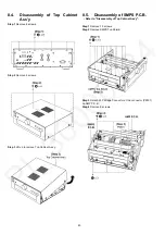
Step 5 Detach 30P FFC at the connector (P6502) on AMP
P.C.B..
Step 6 Detach 40P FFC at the connector (P6503) on AMP
P.C.B..
Step 7 Detach 23P Bridge Connector at the connector (P6001)
on AMP P.C.B..
Step 8 Detach 7P Cable at the connector (P6801) on AMP
P.C.B..
Step 9 Remove AMP P.C.B..
8.7.
Disassembly of Speaker L
P.C.B. and Speaker R P.C.B.
• Refer to “Disassembly of Top Cabinet Ass’y”.
Note:
The disassembling procedure for Speaker L P.C.B. will be
described here.
For Speaker R P.C.B., please refer to the same prodecure
described here.
Step 1 Remove 1 screw.
Step 2 Remove 2 screws.
Step 3 Remove 2 nuts.
Step 4 Remove Speaker L P.C.B..
8.8.
Disassembly of Control P.C.B.
• Refer to “Disassembly of Top Cabinet Ass’y”.
Step 1 Remove 1 screw.
Step 2 Remove 1 screw.


