background image

AD0104089C2

Stereo Integrated Amplifier

SU-V300M2

Colour

(K)...........Black Type

Areas

(E)...........Europe.

(EB).........Great Britain.

(EG).........Germany.

SPECIFICATIONS

1

Summary of Contents for SU-V300M2

Page 1: ...AD0104089C2 Stereo Integrated Amplifier SU V300M2 Colour K Black Type Areas E Europe EB Great Britain EG Germany SPECIFICATIONS 1...

Page 2: ...changed from Model No SU V300M2 Order No AD99003072C2 This model SU V300M2 Order No AD0104089C2 is changed from Model No SU V300M2 Order No AD9903072C2 about Printed Circuit Board So you need to use t...

Page 3: ...voltage controller to make sure that the consumed current at 50 Hz in NO SIGNAL mode should be shown below with respectto supply voltage 230 240 V Power supply voltage AC 230 V AC 240 V Consumed curr...

Page 4: ...ctions the unit will not operate unless the power is first switched OFF and then ON again 4 Accessories AC power supply cord for E and EG areas RJA0019 1X 1 pc AC power supply cord for EB area RJA0035...

Page 5: ...t Procedures This section describes procedures for checking the operation of the major printed circuit boards and replacing the main components For reassembly after operation checks or replacement rev...

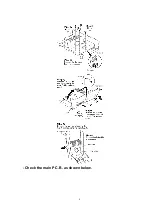
Page 6: ...described only when required 7 1 Checking for the operation P C B and tone amp P C B Check the operation P C B and tone amp P C B as shown above 6...

Page 7: ...7 2 Checking for the main P C B Follow the Step 1 Step 5 of item 7 1 7...

Page 8: ...Check the main P C B as shown below 8...

Page 9: ...7 3 Replacement for the power IC Follow the Step 1 Step 3 of item 7 1 9...

Page 10: ...8 Type Illustration of ICs Transistors and Diodes 9 Schematic Diagram Notes This schematic diagram may be modified at any time with the development of new technology 10...

Page 11: ...TAPE1 MONITOR S807 Unit on off switch S808 Speaker select switch SPEAKERS A S809 Speaker select switch SPEAKERS B VR471 Bass control VR BASS VR472 Treble control VR TREBLE VR501 Volume control VR VOLU...

Page 12: ...hen replacing any of components be sure to use only manufacturer s specified parts shown in the parts list The supply part number is described alone in the replacement parts list Caution IC and LSI ar...

Page 13: ...no signal line Rec out signal line 10 Schematic Diagram 11 Printed Circuit Board Diagram 12 Wiring Connection Diagram 13 Block Diagram 14 Terminal Function of ICs 14 1 IC801 M37470M2536S Micro Compute...

Page 14: ...ive signal output 6 P12 T0 O LED AUX drive signal output 7 P11 O LED TAPE2 drive signal output 8 P10 O LED TAPE1 MONITOR drive signal output 9 P23 IN3 Motor volume control drive signal output Not used...

Page 15: ...8 P03 O LED SPEAKER A drive signal output 29 P04 O LED SPEAKER B drive signal output 30 P05 Not used connected to GND 31 P06 Not used 32 P07 O Audio muting control signal output 15 Replacement Parts L...

Page 16: ...NET 1 3 XTBS3 8JFZ1 SCREW 17 4 RGW0201 K KNOB VOLUME 1 5 RHD30070 SCREW 1 6 RKA0053 A FOOT 4 7 RMG0332 K RUBBER 2 8 RGP0389G K1 FRONT PANEL 1 9 RGB0031 A TECHNICS BADGE 1 10 RGL0184A Q1 PANEL LIGHT 1...

Page 17: ...489 90 ECQB1H392JF3 50V 3900P 2 C491 92 ECFR1E273KR 25V 0 027U 2 F1C1E273A011 C495 96 ECBA1E103ZF5 25V 0 01U 2 ECBT1E103ZF5 C518 ECBA1E103ZF5 25V 0 01U 1 ECBT1E103ZF5 C561 62 ECBT1H102KB5 50V 1000P 2...

Page 18: ...IODE 2 MA2C165 D604 MA4160M DIODE 1 MAZ41600M D606 08 MA165 DIODE 3 MA2C165 D701 04 P300DLF DIODE 4 B0EAMM000025 D705 MA4150M DIODE 1 MAZ41500M D706 MA4075M DIODE 1 MAZ40750M D707 1SR35200TB DIODE 1 B...

Page 19: ...P C B ASS Y 1 RTL E EG PCB3 REP3183B P P C B ASS Y 1 RTL EB Q505 08 2SD1915FTA TRANSISTOR 4 Q601 05 2SC3311AR TRANSISTOR 5 Q606 2SA1309AR TRANSISTOR 1 Q702 2SD2037EFTA TRANSISTOR 1 Q751 2SC2458GR TRAN...

Page 20: ...R459 60 ERDS2FJ680 1 4W 68 2 20...

Page 21: ...63 1 4W 56K 2 R605 06 ERDS2FJ272 1 4W 2 7K 2 R607 08 ERDS2FJ563 1 4W 56K 2 R609 10 ERDS2FJ470 1 4W 47 2 R611 12 ERDS1FJ100 10 2 R619 ERDS2FJ124 1 4W 120K 1 R620 ERDS2FJ682 1 4W 6 8K 1 R623 ERDS2FJ684...

Page 22: ...RDS2FJ331 1 4W 330 1 R828 ERDS2FJ102 1 4W 1K 1 R829 ERDS2FJ103 1 4W 10K 1 R830 ERDS2FJ472 1 4W 4 7K 1 R831 ERDS2FJ331 1 4W 330 1 R832 ERDS2FJ105 1 4W 1M 1 R833 ERDS2FJ334 1 4W 330K 1 R834 ERDS2FJ103 1...

Page 23: ...23...

Page 24: ...17 Packaging 24...

Page 25: ...F010400000YM KH 25...

Page 26: ...9 B C E Q808 B C E Q807 B C E Q806 B C E Q805 B C E Q804 B C E Q803 J J J J J J J J J J J J J J J J J J J J J 1 2 3 4 5 6 7 8 CP901 1 2 3 4 5 6 7 8 CP902 J J D802 D802 D801 R829 R801 R803 R805 D806 D8...

Page 27: ...TREBLE VR472 2 VR472 1 E401 J C482 C807 C481 C484 C472 C471 C483 J J J J J J J J J R479 R534 R833 R832 R831 R834 R533 R490 R480 R478 R476 R825 R532 R477 R475 C479 C477 VR502 BALANCE C490 1 2 3 4 5 6 7...

Page 28: ...450 R455 R458 R460 C456 C466 R451 R449 R457 1 4 5 8 IC451 C460 C462 C465 C459 C461 R462 R459 R461 R463 R464 R466 C464 C463 R468 R465 R467 J J J J J J J J J J J J J J J C402 C404 R430 R426 R425 R427 C4...

Page 29: ...5 6 1 3 2 4 RL751 FP701 FC1 F1 T1A L1 JK791 POWER SUPPLY P C B F POWER TRANSFORMER P C B G REP3183A P EZ EGZ REP3183B P EBZ REP3183A P EZ EGZ REP3183B P EBZ CN755 CN754 CN753 CN752 CN751 T1 Power tra...

Page 30: ...T 1 2 3 4 5 6 7 8 To MAIN CIRCUIT CN901 on SCHEMATIC DIAGRAM 3 E SCHEMATIC DIAGRAM 1 To MAIN CIRCUIT CN902 on SCHEMATIC DIAGRAM 3 E R806 10K C B E D R829 10K 17 18 19 20 21 22 23 24 25 26 27 28 29 30...

Page 31: ...4 MA165TA R819 560 D818 LN018304P SPEAKERS A D823 MA165TA R820 560 D819 LN018304P SPEAKERS B Q813 814 UN4111TA LED DRIVE Q814 Q813 Q810 UN4211TA LED DRIVE C561 1000P C562 1000P C477 220P C479 56P R479...

Page 32: ...467 1K R463 12K R461 180K C459 0 022 C461 6800P R459 68 C463 35V4 7 R465 56K C455 1000P C456 1000P C460 0 022 C462 6800P R460 68 R462 180K R464 12K R468 1K C466 0 01 C464 35V4 7 R466 56K R449 120 R450...

Page 33: ...60 1000 R756 1K D710 MA4051MTA C756 0 01 D707 1SR35200TB D708 MA167ATA R725 15K Q702 2SD2037EFTA REGULATOR C623 0 015 C624 0 015 C622 0 015 C621 0 015 L601 0 7 H R609 47 R610 47 C611 0 1 R611 10 C612...

Page 34: ...0TB Q751 2SC3312RSTTA RELAY DRIVE R752 4 7K C775 3900P R751 1 2K D754 MA165TA POWER SUPPLY CIRCUIT F 1 2 3 CN757 L1 T1 230 240V 50 60Hz JK791 AC IN F1 T1A L1 T1 C625 270P R754 330 R753 330 5 1 3 6 4 2...

Page 35: ...hode A Ca 2SD2037EFTA UPC4570C NJU7312AL AN6558F 8PIN 28PIN 8PIN M5218AP M37470M2536S 2SC3327ABTP DTA124ESTP MA4150MTA MA4160MTA MA4240MTA MA165TA MA167ATA 1SR35200TB 1SS291TA P300DLF LN014304P LN0183...

Page 36: ...1 CP902 CP906 E MAIN P C B F POWER SUPPLY P C B G POWER TRANSFORMER P C B CN906 1 8 8 1 CP903 1 8 CP904 CP905 1 7 CP601 7 1 CN601 1 8 CN901 1 8 CN902 1 8 CN904 1 8 CN903 1 6 CN701 TUNER AUX CD SPEAKE...

Page 37: ...a small amount of power When the unit is connected to the AC mains supply the indica tor lights up in standby mode and goes out when the unit is turned on No Name 2 Operation indicator OPERATION When...

Page 38: ...1 IN1 P20 IN0 P07 P15 S OUT P14 S IN P13 T1 P12 T0 P11 P10 8 HEADPHONES 27 26 P02 P01 treble bass NF MUT ING BIAS SHORT DET POWER ON OFF Drive Power 10 14 11 13 4 1 Q601 RL601 A SPEAKERS B Q602 RL602...

Reviews: