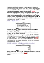
All the dots light red, green, blue, white, and finally black. The
display can be held by pressing the DISPLAY HOLD button.
CROSSTALK:
An H pattern is shown. LCD crosstalk can be evaluated. To exit
this test, press the EXIT button.
SAMPLE:
Several display patterns shown during normal use are shown. The
display can be held by pressing the DISPLAY HOLD button.
CONTRAST:
The test pattern is shown. Adjust the contrast by the CONTRAST
control on the left of the LCD. To exit this test, press the EXIT
button.
- If the correct display is not shown during these tests, the LCD or
LCD drive circuit may be defective.
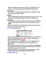
12.7. In & Out interface test
Fig.28
- The operation status of each input action part can be confirmed. If
the part is operating properly, “OK” is shown, excluding the
Expression Pedal. (refer to
Fig.28
)
- When a keyboard key is pressed, the corresponding pitch and
velocity aftertouch is displayed (only as long as the key is
depressed).
- The respective statuses for other input action parts are displayed.
(Analog parts are shown as numerical values from 0 to 255, and
switches are shown as ON or OFF.)
- If the display fails to change when the part is operated, or if the
change is abnormal, it may indicate a defective part.
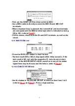
12.8. MIDI IN/OUT test
Fig.29
22
Summary of Contents for SX-KN6500
Page 8: ...10 Parts Location 8...
Page 30: ...30...
Page 37: ...C26 ECUV1H104ZFX 50V 0 1 1 MAIN SPC 37...
Page 49: ...L1 QLBG003A COIL 1 MAIN SPC 49...
Page 51: ...PCB18 SXPG232941 ACP P C B 1 EG EZ EB RTL M 51...
Page 55: ...R19 ERDS2TJ103 1 4W 10K 1 CPL SPC 55...
Page 63: ...X301 QSIG1I3000A 30MHZ CERAMIC OSCILLATOR 1 MAIN M 63...
Page 66: ...22 Manual Keyboard Parts and Control Panel Parts Location 66...
Page 67: ...67...


