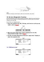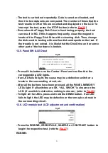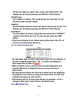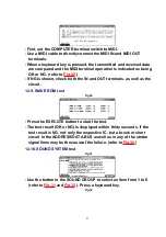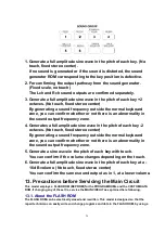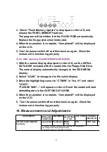
3. Check “Flash Memory Update” is displayed on the LCD, and
release the PANEL MEMORY buttons.
The program will be written into the FLASH ROM automatically.
Replace the floppy disk when instructed.
4. When the operation is complete, “Completed!!” will be displayed
on the LCD.
5. Turn the power switch off and then back on again. Check the
instrument is functioning properly.
13.4.2. After replacing the CUSTOM DATA ROM (IC18)
1. With the normal display displayed on the LCD, set the INITIAL
DATA DISK included with the model into the Floppy Disk Drive.
The normal display automatically changes to the DISK MENU
display.
2. Select “LOAD” to change to the file select display.
3. Move the highlighting cursor to “CTMINI” in “No. 01” and select
“LOAD”.
“PLEASE WAIT...” will appear on the LCD and the model will start
defaulting data in the CUSTOM DATA ROM.
4. When the operation is complete, “Completed!!” will be displayed
on the LCD.
5. Turn the power switch off and then back on again. Check the
instrument is functioning properly.
14. Measurements and Adjustments
ADJUSTMENT
MEASURING
CONDITIONS
EQUIPMENTADJUSTMENT
P.C.B.
ADJ. POINT
CONNECT
METER TO
METER
READING
AFTER TOUCH SENSOR
Sensitivity
any position Oscilloscope MKB3
P.C.B.
VR1
CN11-3pin
6.0V
1. Press one of the any keys hardly and check the CN11-3 pin voltage.
The voltage will increase and become steady.
2. Adjust the voltage to 6.0V with VR1 at that time.
26
Summary of Contents for SX-KN6500
Page 8: ...10 Parts Location 8...
Page 30: ...30...
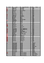
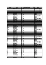
Page 37: ...C26 ECUV1H104ZFX 50V 0 1 1 MAIN SPC 37...
Page 49: ...L1 QLBG003A COIL 1 MAIN SPC 49...
Page 51: ...PCB18 SXPG232941 ACP P C B 1 EG EZ EB RTL M 51...
Page 55: ...R19 ERDS2TJ103 1 4W 10K 1 CPL SPC 55...
Page 63: ...X301 QSIG1I3000A 30MHZ CERAMIC OSCILLATOR 1 MAIN M 63...
Page 66: ...22 Manual Keyboard Parts and Control Panel Parts Location 66...
Page 67: ...67...


