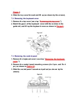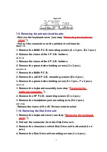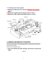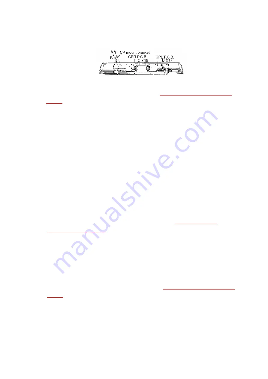
Figure-16
7.9. Removing the printed circuit boards
- Remove the keyboard cover (see step “
Removing the keyboard
cover
”).
- Pull out the connectors on the printed circuit boards.
MAIN P.C.B.
1. Remove the MAIN P.C.B. mounting screws (A x 2 pcs., B x 3 pcs.).
2. Release the claws of the 3 P.C.B. holders.
AS P.C.B.
1. Release the claws of the 9 P.C.B. holders.
2. Remove the ground wire holding screws (C x 2 pcs.).
JACK P.C.B.
1. Remove the MAIN P.C.B..
2. Remove the JACK P.C.B. mounting screws (D x 4 pcs.).
3. Remove the ground wire holding screw (E x 3 pcs., F x 2 pcs.).
HP P.C.B.
1. Remove the keyboard assembly (see step “
Removing the
keyboard assembly
”).
2. Remove the HP P.C.B. mounting screws (G x 2 pcs.)
3. Remove the headphone jack mounting nuts (H x 2 pcs.).
ACP P.C.B.
- Release the claws of the AC IN connector bracket.
7.10. Removing the Disk Drive unit
1. Remove the keyboard cover (see step “
Removing the keyboard
cover
”).
2. Pull out the connector from the Disk Drive unit.
3. Remove the chassis on which Disk Drive unit is attached (I x 4
pcs.).
4. Remove the Disk Drive unit mounting screws (J x 4 pcs.).
13
Summary of Contents for SX-PR603/M
Page 33: ...C15 ECCR1H100D5 10PF 1 AS 33...
Page 38: ...D12 MA165 DIODE 1 MKB1 38...
Page 47: ...L8 QLQGT1D600MA COIL 1 AS 47...
Page 50: ...50...
Page 59: ...59...
Page 60: ...60...
Page 61: ...18 PACKAGING 61...


