background image

PG 16

PG 17

SOLVING PROBLEMS

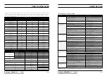
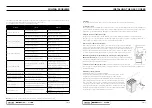
If you have a problem with your appliance, check the table below before calling service. You may be able to avoid 
a service call by and avoid unnecessary inconvenience and expense.
For cooking problems, refer to Handling Baking Problems.

NOTE: 

Only service centers should carry out servicing. Otherwise warranty may be void.

Problem

Causes

Remedy

Elements won’t work

Circuit breaker tripped

Check circuit breaker

Household fuse blown

Replace household fuse

Oven or grill not working

120 min Timer now in Manual position

Refer to 120 min timer instructions

Power not turned on

Switch on electricity

Control is incorrectly set

Reset controls

Circuit breaker tripped

Check circuit breaker

Oven light not working

Power not turned on

Switch on electricity

Household fuse blown

Check fuses

Circuit breaker tripped

Check circuit breaker

Lamp blown or loose in socket

Replace or tighten globe

Oven not hot enough

Heat escaping through incorrectly 
sealed door

Check shelves or dishes are not 
preventing door closing properly. 
Check that door is fitted properly after 
door removal for cleaning

Door seal is worn or has moved

Replace seal or re set it

Unit smoking when first used

Protective oils being removed

This is normal

Odour on first use of oven

Manufacturing oils on elements

This is normal

120minute timer buzzer not 
audible

Timer not wound sufficiently

Allow 2-4 hours for odour to dissipate 
(open all windows)

Oven shelf tight

Oven shelf not inserted corectly, may 
be upside down or back to front

Turn timer knob past 15 minute mark. 
Then turn to the required number of 
minutes.

Clock display off

Household fuse blown or power 
supply is off

Remove shelf and insert as per 
diagram
Check fuses, power supply

INSTALLING THE GAS COOKER

Unpacking

Do not fit the burner crowns, burner caps and trivets until after the cooker has been installed.

Locating the cooker

This appliance must be installed by an authorised person in accordance with this instruction manual, AS/NZS 5601 
– Gas installations (installation and pipe sizing), local gas fitting regulations, local electrical regulations, local water 
regulations, local health regulations, Building Code of Australia and any other government authority.

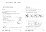
Overhead clearances—(Measurement A) 

Range hoods and exhaust fans shall be installed in accordance with the manufacturer’s relevant instructions. 
However, in no case shall the clearance between the highest part of the hob of the gas cooking appliance and a 
range hood be less than 600 mm or, for an overhead exhaust fan, 750 mm

Side clearances—(Measurements B, & C) 

Where B, measured from the periphery of the nearest burner to any vertical combustible 
surface, or vertical combustible surface covered with toughened glass or sheet metal, is less 
than 200 mm, the surface shall be protected to a height C of not less than 150 mm above 
the hob for the full dimension (width or depth) of the cooking surface area. Where the gas 
cooking appliance is fitted with a ‘splashback’, protection of the rear wall is not required.

Additional requirements for freestanding and elevated gas cooking appliances— 
(Measurements D & E).

 Where D, the distance from the periphery of the nearest burner to 

a horizontal combustible surface is less than 200 mm, then E shall be 10 mm or more, or the 
horizontal surface shall be above the trivet.

Overheat clearances -(Measurement A): 

The distance between the highest part of the 

hob of the gas cooking appliance should be higher than 600mm for a range hood and higher than 750mm for an 
overheat exhaust fan.

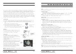
Installation of the anti-tilt plate

Determine position of cooker and anti-tilt plate.
Securely fix the anti-tilt plate to the floor with appropriate fasteners. Fasten 
the stability bolt bracket to the front grame with the 2 screws supplied. 
Reposition the cooker back into the anti-tilt plate and then mark the position 
of the stability bolt hole. Pull the cooker back out and drill the bolt location 
hole. Use a 10mm masonry or wood drill. When drilling into concrete ensure 
a minimum hole depth of 30mm. Reposition the cooker back into the anti-tilt 
plate, aligning the stability bolt bracked with the 10mm drilled hole. Then slide 
the bolt through the bracket and into the hole. Connect Electricity supply/gas 
supply but do not turn on until installation is completed.

Summary of Contents for TFS54FC-SGW

Page 1: ...USER GUIDE 5 4 C M F R E E S T A N D I N G G A S C O O K E R T F S 5 4 F C S G W TECHNIKA COM AU ...

Page 2: ...ems Pg 16 Connection to the gas supply Pg 17 Installing the gas cooker Pg 19 Testing the operation of the gas cooker Pg 20 Technical specifications Pg 22 Warranty Pg 22 We recommend that you read the instructions in this manual carefully before use for the best performance and to extend the life of your appliance as it will provide you with all the instructions you require to ensure its safe insta...

Page 3: ... current laws and regulations by qualified tradesmen Installers Gas models are NOT APPROVED for installation in marine craft caravans or mobile homes The Manufacturers and Importers Distributors and Retailers shall not be liable to any legal liability personal injury and property damage due to incorrect operation or incorrect Installation The Manufacturers Importers Distributors and Retailers shal...

Page 4: ... sodabased cleaners Using warm soapy water after the appliance has cooled somewhat followed by a dry cloth is suitable DO NOT use sharp metal scrapers to clean oven door as they can scratch the surface which may result in shattering of the glass DO NOT use steam cleaners as a method to clean this appliance Always clean the appliance immediately after any food spillage To be serviced only by an aut...

Page 5: ...re the is on the inner side Then insert the battery Place the cover on and turn clockwise to complete installation Battery ignition control Completely open the oven door turn the temperature knob anti clockwise to the highest temperature setting and press in the igniter Once burner is ignited hold the temperature knob in for a few seconds to allow it to heat up If the burner is not lit after 15 se...

Page 6: ...rature Food too low in oven Cook one shelf higher Cake batter over mixed Mix just long enough to combine the ingredients Baking tin too deep or wrong size Check size of tin and use recommended size Bked products are pale flat and under cooked Baking tins dark Change to shiny light tins Baking temperature too low Raise the temperature Food too low in oven Cook one shelf higher Baking time too short...

Page 7: ...se 2 Turn the burner control knob to 3 Press the body release spark burner switch Burner 1 Rapid Burner Used for normal cooking 2 Semi rapid Burner Used with middle size pots and pans 3 Auxiliary Burner Used for simmering Used with small pots and pans To conserve gas place the pan centrally over the burner and adjust the flame so that it does not go past the edges of the cookware Get to know your ...

Page 8: ...wn must be fitted correctly into the burner cup or damage will occur during operation To do this ensure that the 2 ribs on either side of the spark plug hole are positioned into the 2 slots on the burner cup See figure 2 The burner cap is simply positioned over the top of the burner crown NOTE When the burner is correctly fitted it will sit level on the knob If ignition is difficult or fails after...

Page 9: ...g local gas fitting regulations local electrical regulations local water regulations local health regulations Building Code of Australia and any other government authority Overhead clearances Measurement A Range hoods and exhaust fans shall be installed in accordance with the manufacturer s relevant instructions However in no case shall the clearance between the highest part of the hob of the gas ...

Page 10: ...ter zero point is correct Connect the manometer to the cooker pressure test point This is located on the regulator or LPG inlet fitting Turn on the gas supply and the electricity if applicable and try to ignite the gas NOTE It will take additional time to light the gas for the first time as air needs to be purged from the pipes Check the operating pressure for the particular gas type see table For...

Page 11: ...lified person in order to avoid a hazard Unpacking and installation instructions for installer Please check the product and make sure that there is no damage Read the relevant installation sections of this manual 16 17 18 19 Ensure understanding Confirm that product is compatible with available electrical gas supply Ensure proposed installation position does not conflict with installation sections...

Page 12: ...allation insect or vermin infestation improper liquid spillage cleaning or maintenance unauthorised modification use on an incorrect voltage power surges and dips voltage supply problems tampering or unauthorised repairs by any persons use of defective or incompatible accessories or exposure to abnormally corrosive conditions events independent of human control which occurred after the goods left ...

Page 13: ...necessary and useful without affecting the essential safety and operating characteristics Glen Dimplex constantly seeks ways to improve the specifications and designs of their products Whilst every effort is made to produce up to date literature this document should not be regarded as an infallible guide Actual product only should be used to derive cut out sizes All appliances must be installed by...

Reviews: