background image

Installation 

Preparation 

  A 

safety valve

 (max. 8 bar) must be installed in the cold water supply corresponding


to standards DIN 1988 und 4753, part 1 and TRD 721. 


  If the cold water pressure > 8 bar, fit a 

diaphragm


pressure reducer 

max. 8 bar. 

  The installation of 

flushing equipment

 before and after the plate heat exchanger in 

the primary and secondary circuits is recommended for descaling or cleaning as nec-
essary. 

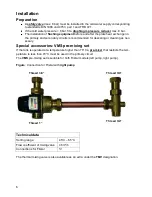
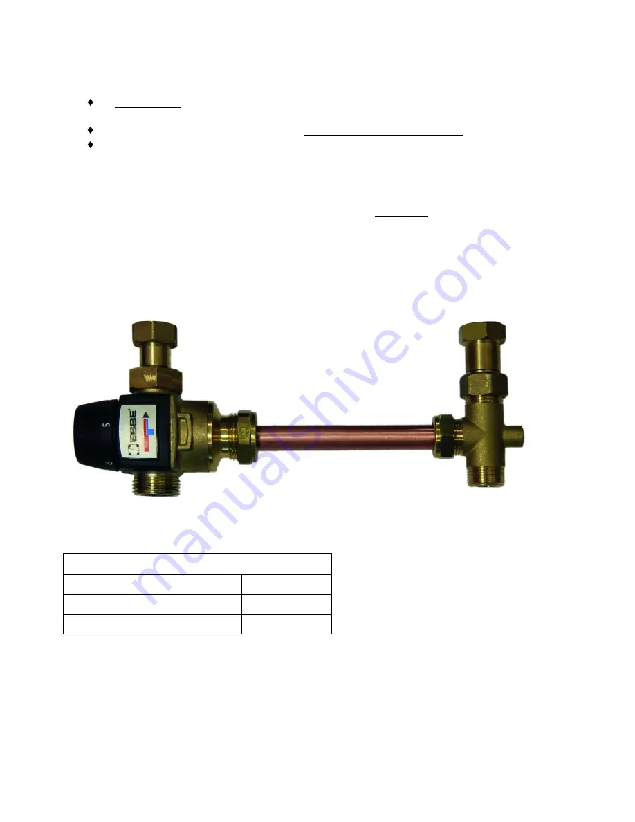
Special accessories: VMS pre-mixing set 

If the tank is operated at a temperature higher than 70°C a 

pre-mixer

 that restricts the tem-

perature to less than 70°C must be used in the primary circuit. 

The 

VMS

 pre-mixing set is suitable for both Fristar models (left pump, right pump). 


Figure

: Connection for Fristar with 

right pump


Technical data 

Setting range: 

45°C 

– 65°C 

Flow coefficient of mixing valve 

4.5m³/h 

Connections for Fristar 

¾” 


The thermal mixing valve is also available as an extra under the 

TMV

 designation.


Thread 3/4“ 

Thread 3/4“ 

Thread 3/4“ 

Thread 1

“ 

Summary of Contents for FRISTAR

Page 1: ...FRISTAR Version 2 01 EN Manual version 3 Fresh water station Operating manual en...

Page 2: ...diagram of a cascade with four FRISTAR fresh water stations 11 Cascade switching control with UVR61 3R or UVR63 12 Control of cascade switching with UVR1611 13 Cascade switching with circulation line...

Page 3: ...es provided in the insulated base in such a way that direct contact with the pump casing and the pipes is prevented Before switching on check whether the supply voltage matches that stated on the powe...

Page 4: ...ater is returned to bottom layer of the buffer tank The speed control of the primary circuit pump takes place in the FRISTAR controller based on the measurements of the volume flow sensor in the hot w...

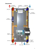
Page 5: ...all valve Ball valve with gravity brake Ball valve Ball valve Hot water Secondary circuit Cold water Secondary circuit Volume flow sensor Primary sensor Controller Pump Power cable Plate heat exchange...

Page 6: ...ling or cleaning as nec essary Special accessories VMS pre mixing set If the tank is operated at a temperature higher than 70 C a pre mixer that restricts the tem perature to less than 70 C must be us...

Page 7: ...this the locking bolt of the return valve with the gravity brake is placed in a 45 position so that it is non operational Slowly fill the house system with drinking water via the secondary side ball...

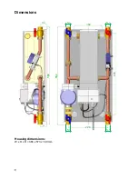
Page 8: ...8 Dimensions Housing dimensions W x H x D 366 x 573 x 160 mm 38 38 160 470 562 562 228...

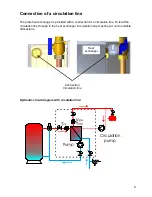
Page 9: ...with a connection for a circulation line To lead the circulation line through to the heat exchanger the isolation cap must be cut out to suitable dimensions Hydraulic circuit diagram with circulation...

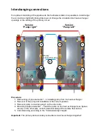
Page 10: ...Demounting of pipe elements 1 4 including pump from the heat exchanger 2 Removal of the pump and installation in the correct position 3 Remount pump connection plug 5 on the other side 4 Mounting of...

Page 11: ...e than 40 litres per minute the overriding controller must increase the number of stations in steps of approx 8 10 l min This ensures that the sensors in the FRISTAR stations are not strained excessiv...

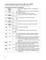
Page 12: ...ting 8 Par All three max input and output thresholds are left with factory settings 75 70 C because they do not influence control 9 Par Because the flow values of the sensors are displayed as temperat...

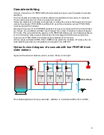
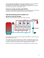
Page 13: ...off thresholds are identical to those of the UVR61 3 Cascade switching with circulation line Hydraulics schematic diagram Figure with fresh water stations version version Pump on the right The circul...

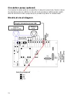
Page 14: ...the run time 20 or 40 seconds set with the selector switch After the end of the run time pump start up is permitted only after a 10 minutes break Electrical circuit diagram Plug for volume flow sensor...

Page 15: ...ller settings ON EIN The pump is switched on continuously at full speed independent of the control temperature Selection switch runtime circulation pump The selection occurs by means of a slide switch...

Page 16: ...ry G external thread Materials corresponding to DVGW W270 Fittings Brass CW617N Heat exchanger Stainless steel 1 4401 copper soldered Pipes Copper 99 96 Seal material PTFE EPDM Klingersil C 4324 Pump...

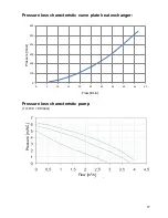
Page 17: ...ss characteristic curve plate heat exchanger Pressure loss characteristic pump 1 m WC 98 mbar Flow l min Pressure mbar Durchfluss m h Pressure m WC Flow m h 0 100 200 300 400 500 600 0 5 10 15 20 25 3...

Page 18: ...H value 7 9 Electrical conductivity 10 500 S cm Free carbonic acid 20 mg l Nitrate 100 mg l Sulphate 100 mg l Saturation index SI 0 2 0 0 2 Total hardness 6 15 dH Filterable substances 30 mg l Free ch...

Page 19: ...ctrical controls for household and similar use Part 1 General requirements EN 61000 6 3 2007 A1 2011 Electromagnetic compatibility EMC Part 6 3 Generic standards Emis sion standard for residential com...

Page 20: ...ation instructions or incorrect maintenance 4 The guarantee claim will expire if repairs or actions are carried out by persons who are not au thorised to do so or have not been so authorised by us or...

Reviews: