RUN EXCITE-2008: Service & Maintenance Manual - rev. 1.3
Page 7.16
7.11.
JOYSTICK DISASSEMBLY
Only fir 700 / 700E and 900 / 900E models.
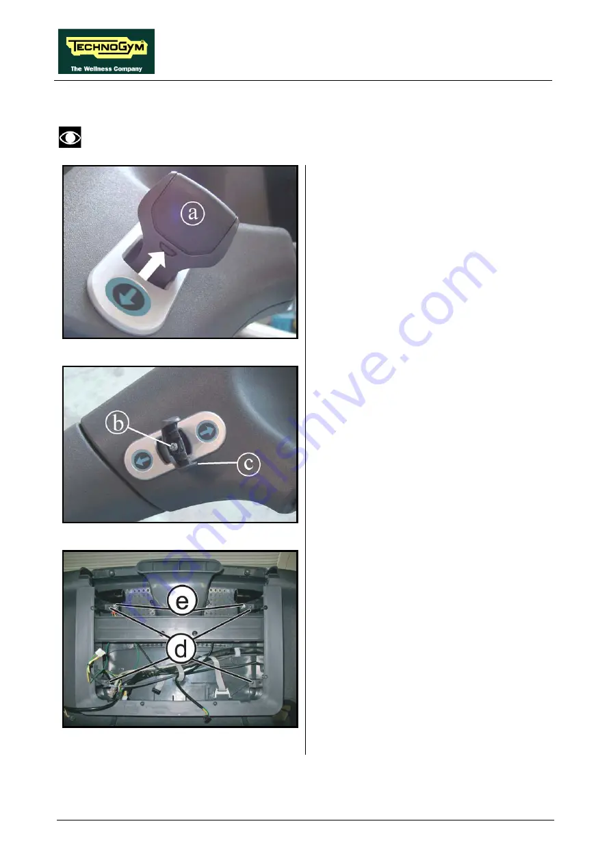
Figure7.11-1
1.
Press on both sides of the joystick lever, at
the point indicated by the arrow, and pull
component
(a)
upward.
Figure7.11-2
2.
Back off the screw
(b)
using a small Phillips
screwdriver.
3.
Remove the joystick lever
(c)
by pulling
upward.
Figure7.11-3
Carry out the procedure described in
paragraph: 7.1. Display disassembly”.
4.
Back off the 4 screws
(d)
using a medium
Phillips screwdriver.
5.
Back off the 2 screws
(e)
using a 5mm
hexagonal wrench.
Continued on following page
→
Summary of Contents for EXCITE Run 500
Page 1: ...D446 D448 D449 SERVICE MAINTENANCE MANUAL REV 1 3...
Page 2: ......
Page 4: ......
Page 32: ...RUN EXCITE 2008 Service Maintenance Manual rev 1 3 Page 2 20 Page intentionally left blank...
Page 52: ...RUN EXCITE 2008 Service Maintenance Manual rev 1 3 Page 3 20 Page intentionally left blank...
Page 59: ...RUN EXCITE 2008 Service Maintenance Manual rev 1 3 Page 4 7 Page intentionally left blank...
Page 60: ......
Page 127: ...RUN EXCITE 2008 Service Maintenance Manual rev 1 3 Page 7 19 Continued on following page...
Page 148: ......
Page 217: ...RUN EXCITE 2008 Service Maintenance Manual rev 1 3 Page 9 63 Page intentionally left blank...
Page 218: ......
Page 229: ...RUN EXCITE 2008 Service Maintenance Manual rev 1 3 Page 11 7 Page intentionally left blank...
Page 230: ......
Page 233: ......


