RUN EXCITE-2008: Service & Maintenance Manual - rev. 1.3
Page 3.9
3.1.14.
ALE
DRIVER
This is the electronic device that receives the line voltage and, through a PFC module, it rectifies
the voltage to the 400 Vdc used to generate the 3 phase voltage for the belt motor. It generates the
DC voltages to power up all the other devices of the machine.
It’s the device that acts as an interconnection hub for the main components of the lower assembly,
and serves as the point of connection with the display. In fact:
•
it supplies the +5Vdc and +12Vdc voltages to the display;
•
it supplies the tread belt motor with a variable-frequency sinusoidal voltage: varying the
frequency varies the speed of rotation of the motor, and consequently the speed of the tread
belt;
•
it supplies the elevation motor and the fans with 24 Vdc voltage;
•
it exchanges, over the RS-485 serial link to the CPU board, the commands for controlling
the tread belt and elevation motors;
•
it exchanges, over the RS-485 serial link to the CPU board, the error signals pertaining to
the tread belt and elevation motors;
•
it exchanges, over the RS-485 serial link to the digital plan board, the commands for
viewing and configuring the inverter parameters;
•
it exchanges, over the RS-485 serial link to the digital plan board, the commands for
viewing the errors logged by the inverter.
From the outside the following indicator LEDs are visible:
LED name
Color
Descriptio
n
H6
Green
+5 Vdc
H3
Green
+12 Vdc
H4
Green
+24 Vdc
H5
Blue
400 Vdc
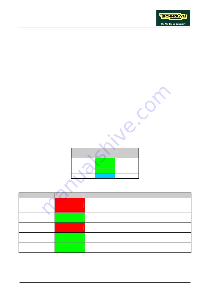
The board includes the following indicator LEDs visible when the driver cover is removed:
LED name
Color
Description
ALARM
Red
If ON indicates that the AT UL driver has detected an error
(EdC) when it was moving the elevation motor. This LED
stay ON for about 1 second and then goes OFF.
EN_UP
Green
if ON indicates that the motor has received the supply
voltage for movement in the upward direction
EN_DOWN
Red
if ON indicates that the motor has received the supply
voltage for movement in the downward direction
TACHO
Green
functioning of elevation motor encoder: if blinking, indicates
that the board is receiving the pulses from the encoder
DWN_SW
Green
status of Limit switch contact: if ON indicates that the
microswitch is pressed
Summary of Contents for EXCITE Run 500
Page 1: ...D446 D448 D449 SERVICE MAINTENANCE MANUAL REV 1 3...
Page 2: ......
Page 4: ......
Page 32: ...RUN EXCITE 2008 Service Maintenance Manual rev 1 3 Page 2 20 Page intentionally left blank...
Page 52: ...RUN EXCITE 2008 Service Maintenance Manual rev 1 3 Page 3 20 Page intentionally left blank...
Page 59: ...RUN EXCITE 2008 Service Maintenance Manual rev 1 3 Page 4 7 Page intentionally left blank...
Page 60: ......
Page 127: ...RUN EXCITE 2008 Service Maintenance Manual rev 1 3 Page 7 19 Continued on following page...
Page 148: ......
Page 217: ...RUN EXCITE 2008 Service Maintenance Manual rev 1 3 Page 9 63 Page intentionally left blank...
Page 218: ......
Page 229: ...RUN EXCITE 2008 Service Maintenance Manual rev 1 3 Page 11 7 Page intentionally left blank...
Page 230: ......
Page 233: ......


