RUN EXCITE-2008: Service & Maintenance Manual - rev. 1.3
Page 7.3
7.2.2.
700E
AND
900E
W
ELLNESS
TV
(UB)
VERSION
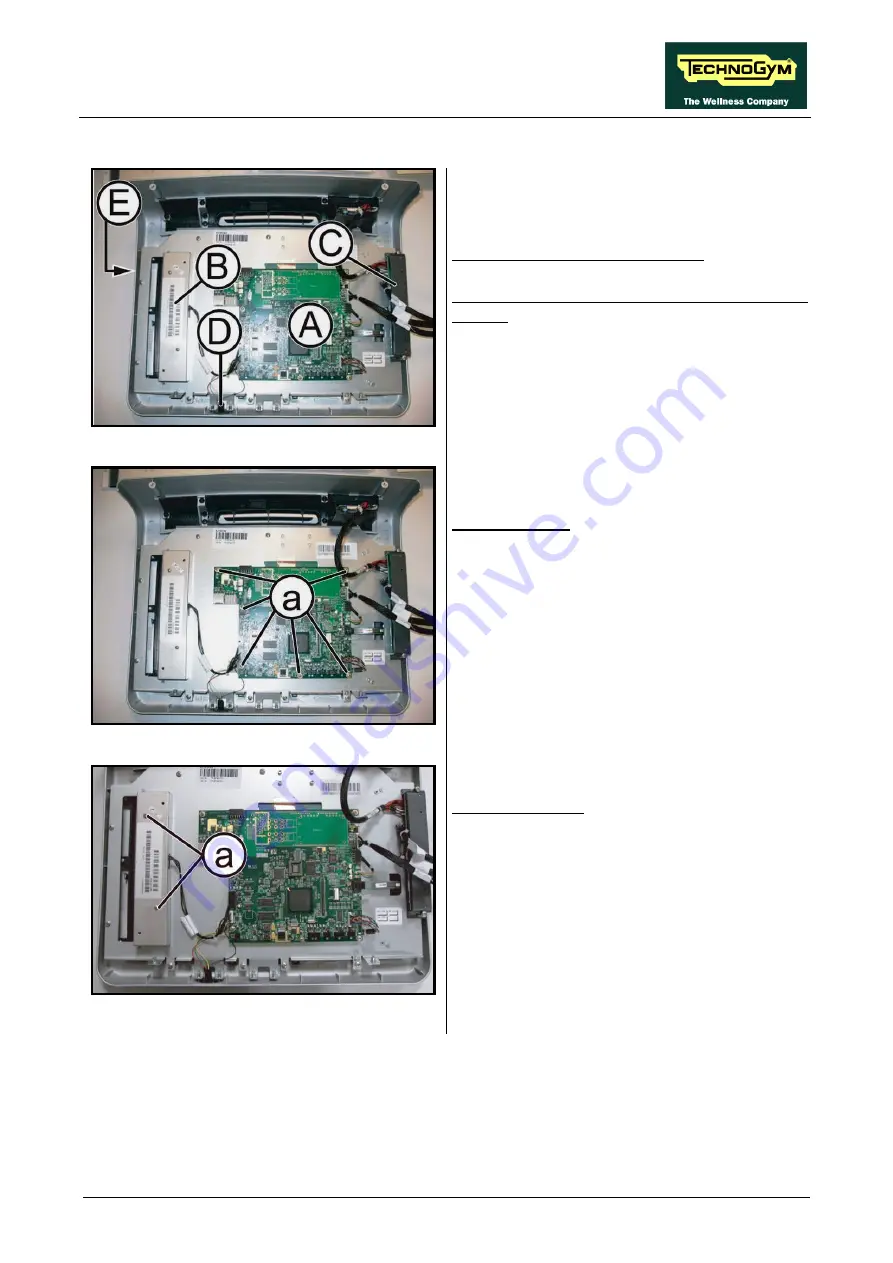
Figure7.2-2
Carry out the operations described in
paragraphs: 7.1. “Display disassembly”.
Place the display on a work bench.
It is now possible to disassemble its circuit
boards:
•
The CPU board
(A)
,
•
The LCD inverter
(B)
,
•
The input AUX board
(C)
,
•
The Headphone Jack
(D)
,
•
The LCD and Touch Screen
(E)
.
Figure7.2-3
CPU board
(A)
:
1.
Disconnect the cables from LCD, LCD
inverter, Touch Screen and Headphone Jack.
2.
Back off the 6 screws
(a)
with a small
Phillips screwdriver.
3.
Remove the CPU board.
Figure7.2-4
LCD Inverter
(B)
:
1.
Back off the 2 screws
(a)
with a small
Phillips screwdriver.
2.
Remove the inverter protection guard.
3.
Disconnect the LCD inverter from CPU
board.
Continued on following page
→
Summary of Contents for EXCITE Run 500
Page 1: ...D446 D448 D449 SERVICE MAINTENANCE MANUAL REV 1 3...
Page 2: ......
Page 4: ......
Page 32: ...RUN EXCITE 2008 Service Maintenance Manual rev 1 3 Page 2 20 Page intentionally left blank...
Page 52: ...RUN EXCITE 2008 Service Maintenance Manual rev 1 3 Page 3 20 Page intentionally left blank...
Page 59: ...RUN EXCITE 2008 Service Maintenance Manual rev 1 3 Page 4 7 Page intentionally left blank...
Page 60: ......
Page 127: ...RUN EXCITE 2008 Service Maintenance Manual rev 1 3 Page 7 19 Continued on following page...
Page 148: ......
Page 217: ...RUN EXCITE 2008 Service Maintenance Manual rev 1 3 Page 9 63 Page intentionally left blank...
Page 218: ......
Page 229: ...RUN EXCITE 2008 Service Maintenance Manual rev 1 3 Page 11 7 Page intentionally left blank...
Page 230: ......
Page 233: ......


