RUN EXCITE-2008: Service & Maintenance Manual - rev. 1.3
Page 8.5
8.4.
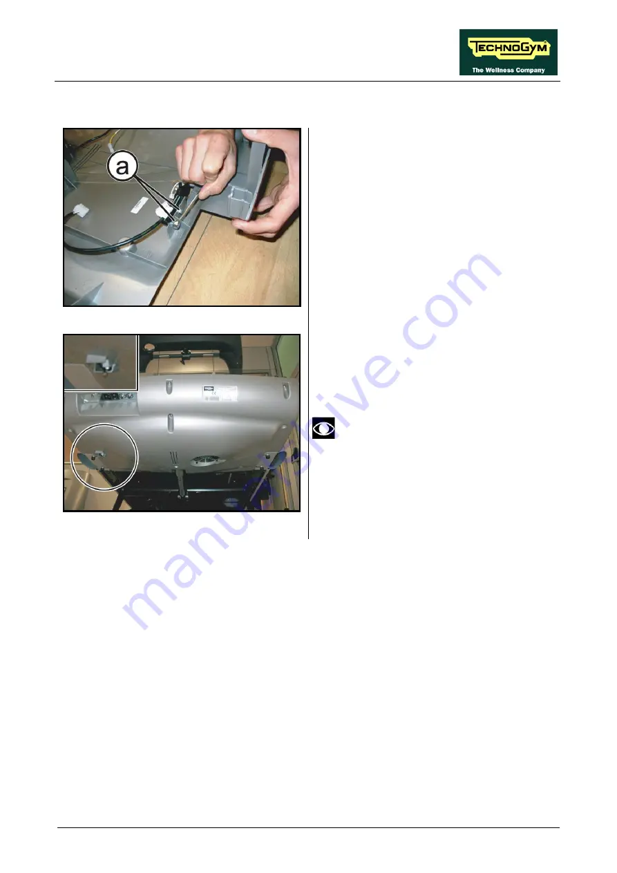
LIMIT SWITCH POSITION
Figure 8.4-1
Carry out the procedure described in
paragraph: 7.12. Motor guard disassembly”.
1.
Loosen the 2 screws
(a)
fixing the limit
switch to the casing.
Figure 8.4-2
2.
Adjust the position of the limit switch so that
it touches the guard without to be pressed.
Take care the limit switch lever is not
pressed on the guard.
3.
After making the adjustment, lock down the
screws
(a)
backed off previously.
Summary of Contents for EXCITE Run 500
Page 1: ...D446 D448 D449 SERVICE MAINTENANCE MANUAL REV 1 3...
Page 2: ......
Page 4: ......
Page 32: ...RUN EXCITE 2008 Service Maintenance Manual rev 1 3 Page 2 20 Page intentionally left blank...
Page 52: ...RUN EXCITE 2008 Service Maintenance Manual rev 1 3 Page 3 20 Page intentionally left blank...
Page 59: ...RUN EXCITE 2008 Service Maintenance Manual rev 1 3 Page 4 7 Page intentionally left blank...
Page 60: ......
Page 127: ...RUN EXCITE 2008 Service Maintenance Manual rev 1 3 Page 7 19 Continued on following page...
Page 148: ......
Page 217: ...RUN EXCITE 2008 Service Maintenance Manual rev 1 3 Page 9 63 Page intentionally left blank...
Page 218: ......
Page 229: ...RUN EXCITE 2008 Service Maintenance Manual rev 1 3 Page 11 7 Page intentionally left blank...
Page 230: ......
Page 233: ......


