JOG EXCITE: Service & Maintenance Manual - rev. 1.1
Page 6.8
(7)
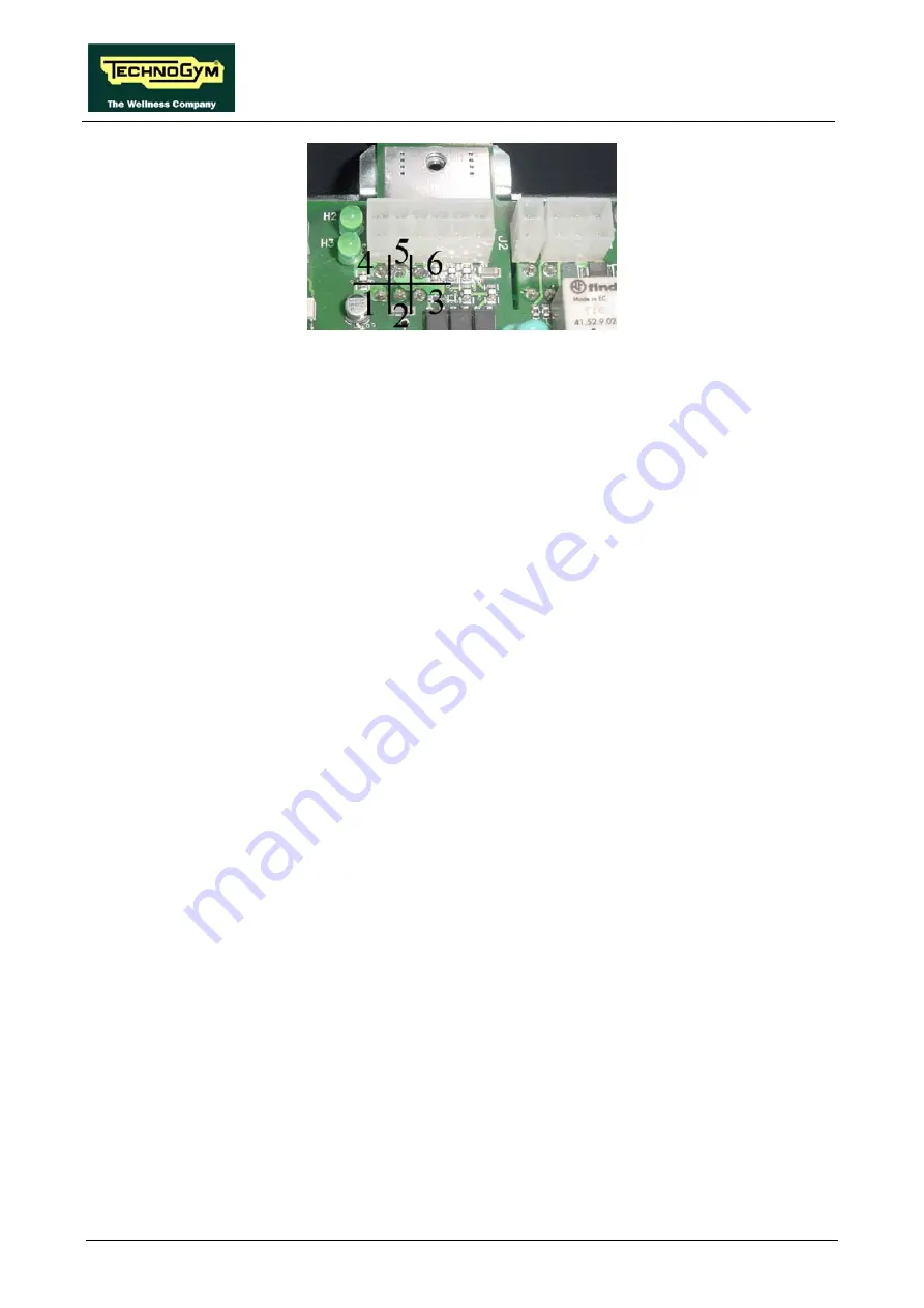
Using a tester, check that the output v12 Vdc on connectors J3 of the AT driver board
are correct, by referring to paragraph 2.7. “Wiring”.
(8)
As for step (7) but on connector CN7 of the display board.
Summary of Contents for JOG EXCITE
Page 1: ...SERVICE MAINTENANCE MANUAL REV 1 1 ...
Page 2: ......
Page 4: ......
Page 20: ...JOG EXCITE Service Maintenance Manual rev 1 1 Page 2 10 Page intentionally left blank ...
Page 68: ...JOG EXCITE Service Maintenance Manual rev 1 1 Page 6 32 Page intentionally left blank ...
Page 125: ......


