JOG NOW : Service & maintenance manual - rev. 6.2
Page 3.29
3.24.3.
UNITY
+
ALEW
IN
(W
ITH
FINAL
CABLES
)
3.24.3.1.
The control
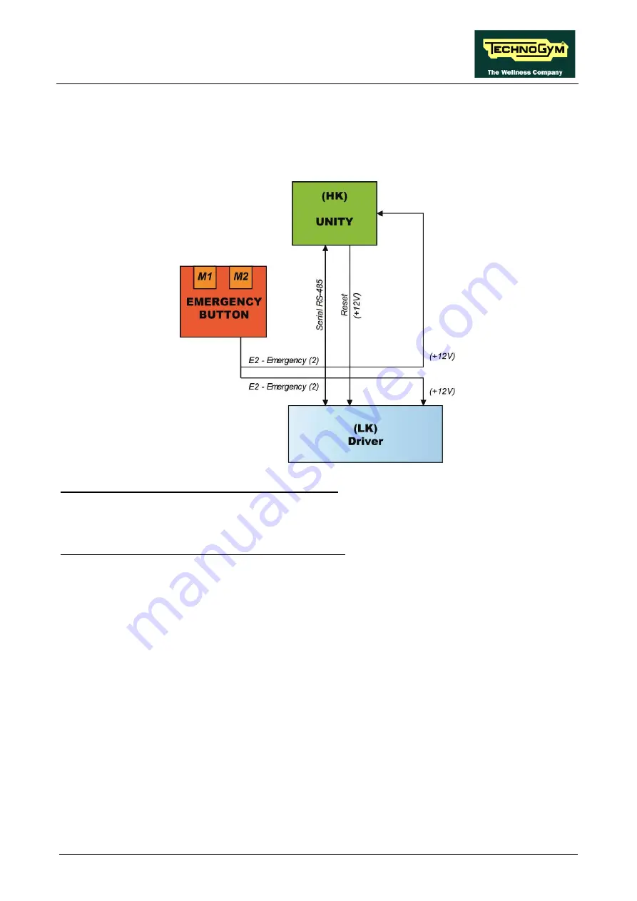
The control block diagram is as follows:
E2 = UNITY (HK)
receives the
Emergency 2
signal.
•
When the system is NOT in emergency the signal is +12V.
•
When you press the EMERGENCY signal goes to GND.
E2 = ALEWin (LK)
receives the
Emergency 1
signal.
•
When the system is NOT in emergency the signal is +12V (pin 8).
•
W When you press the EMERGENCY signal goes to GND.
The two signals are handled at the same time:
•
The EMERGENCY signal generated: is sent to the LK to immediately block it, while the HK
only reads the status of the LK.
To restore operation of the equipment, the user must press any key on the KEYBOARD or on the
Touch Screen.
Pressing a key causes the Driver unlocking procedure to start, and the Driver receives the reset
signal from the Main Board (HK). Following this, the Driver performs the reset procedure. If the
serial communication cannot be successfully established, the equipment will make several attempts
to reset. Every failed connection attempt is recorded in the COM FAULT parameter which can be
displayed as indicated in the paragraph regarding the Service menu. After about 30 seconds it will
interrupt and display the error message on the Display.
Summary of Contents for Jog Now Excite+ 700
Page 2: ......
Page 4: ...JOG NOW Excite Service maintenance manual rev 6 2...
Page 29: ...JOG NOW Excite Service maintenance manual rev 6 2 Page 2 17 UNITY Version...
Page 31: ...JOG NOW Excite Service maintenance manual rev 6 2 Page 2 19 UNITY Version...
Page 186: ...JOG NOW Excite Service maintenance manual rev 6 2 Page 8 6 Page intentionally left blank...
Page 222: ...JOG NOW Excite Service maintenance manual rev 6 2 Pagina 12 2 Blank page...
Page 224: ...JOG NOW Excite Service maintenance manual rev 6 2 Pagina 13 2 Blank page...
Page 226: ......
Page 227: ......


