RECLINE EXCITE: Service & Maintenance Manual - rev. 2.4
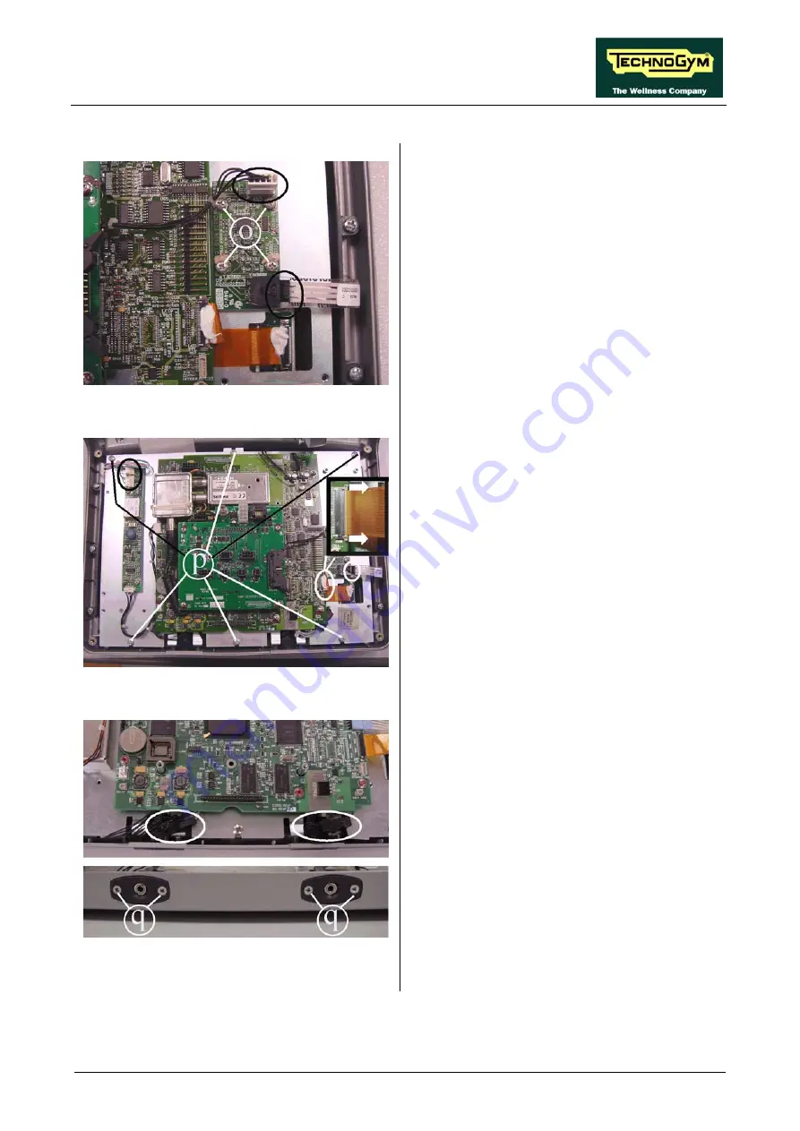
Figure 7.2-10
Touch screen interface board
e
:
1. Unplug the cables on connectors CN1 and
CN5, indicated in the figure, coming from
the touch screen and CPU respectively.
2. Back off the screws
o
using a small Phillips
screwdriver.
3. Remove the circuit board from the display.
Figure 7.2-11
1.
3.
open the connector on the CPU as illustrated
in the close-up at left, and remove the cable.
To disassemble the LCD:
Unplug the connectors of the cables leading
from the touch screen to the touch screen
interface board, to the TTL board and to the
LCD (on the inverter) indicated in the figure.
2. Back off the 6 screws
p
securing the plate
and all the display boards to the front cover.
To unplug the cable from the TTL board,
Figure 7.2-12
4.
ff the 2 screws
q
securing the
er.
6. Remove the two headphone jacks from the
display housing.
7. Lift up the plate to which all the circuit
boards and the LC
Back o
headphone jack to the display, using a small
Phillips screwdriv
5. Unplug the connectors indicated in the
figure.
D are fixed.
→
Page 7.7
Summary of Contents for Recline 500
Page 1: ...SERVICE MAINTENANCE MANUAL REV 2 4...
Page 2: ......
Page 4: ......
Page 10: ...RECLINE EXCITE Service Maintenance Manual rev 2 4 Page vi Page intentionally left blank...
Page 46: ...RECLINE EXCITE Service Maintenance Manual rev 2 4 Page 3 14 Page intentionally left blank...
Page 58: ...RECLINE EXCITE Service Maintenance Manual rev 2 4 Page 4 12 Page intentionally left blank...
Page 94: ...RECLINE EXCITE Service Maintenance Manual rev 2 4 Page 6 34 Page intentionally left blank...
Page 134: ...RECLINE EXCITE Service Maintenance Manual rev 2 4 Page 7 40 Page intentionally left blank...
Page 140: ...RECLINE EXCITE Service Maintenance Manual rev 2 4 Page 8 6 Page intentionally left blank...
Page 172: ...RECLINE EXCITE Service Maintenance Manual rev 2 4 Page 9 32 Page intentionally left blank...
Page 181: ......


