RECLINE EXCITE: Service & Maintenance Manual - rev. 2.4
Page 7.8
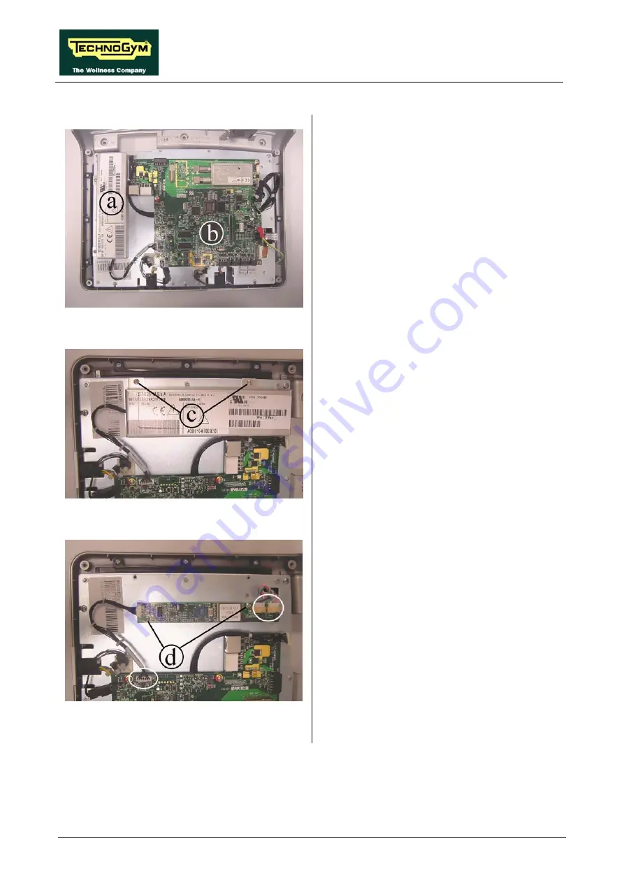
7.2.2.2. UB
models
Figure 7.2-13
e
on a work bench. It is
w
mble its circuit boards:
•
The LCD inverter
a
;
•
The CPU board
b
.
Carry out the procedure described in paragraph
.1. “Disassembling the display”.
7
Th n place the display
no possible to disasse
Figure 7.2-14
LCD inverter
b
:
iver.
1. Back off the two screws
c
using a Phillips
screwdr
2. Raise the inverter cover plate.
Figure 7.2-15
3. Unplug the connectors indicated in the
figure.
4. Back off the two screws
d
securing the board
to the plate of the display.
5. Remove the LCD inverter.
Continued on following page
→
Summary of Contents for Recline 500
Page 1: ...SERVICE MAINTENANCE MANUAL REV 2 4...
Page 2: ......
Page 4: ......
Page 10: ...RECLINE EXCITE Service Maintenance Manual rev 2 4 Page vi Page intentionally left blank...
Page 46: ...RECLINE EXCITE Service Maintenance Manual rev 2 4 Page 3 14 Page intentionally left blank...
Page 58: ...RECLINE EXCITE Service Maintenance Manual rev 2 4 Page 4 12 Page intentionally left blank...
Page 94: ...RECLINE EXCITE Service Maintenance Manual rev 2 4 Page 6 34 Page intentionally left blank...
Page 134: ...RECLINE EXCITE Service Maintenance Manual rev 2 4 Page 7 40 Page intentionally left blank...
Page 140: ...RECLINE EXCITE Service Maintenance Manual rev 2 4 Page 8 6 Page intentionally left blank...
Page 172: ...RECLINE EXCITE Service Maintenance Manual rev 2 4 Page 9 32 Page intentionally left blank...
Page 181: ......


