RECLINE EXCITE: Service & Maintenance Manual - rev. 2.4
Page 7.30
7.15. DISASSEMBLING THE PLATFORMS WITH CSAFE BOARD
CONNECTORS AND POWER ENTRY MODULE
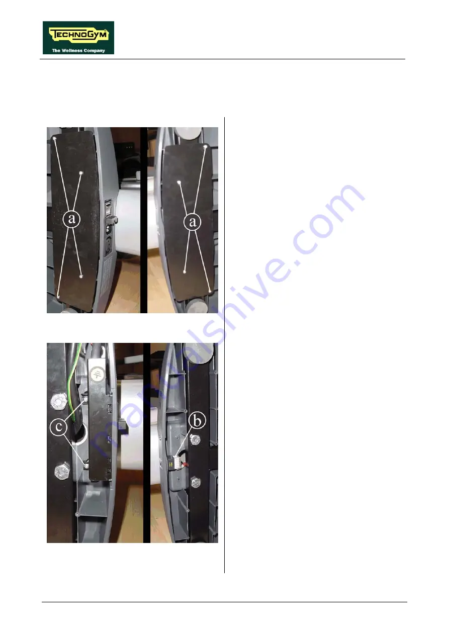
Figure 7.15-1
The front and rear platforms house the following
components:
•
connector of the cable leading to the CSafe
board (front platform, on the right in the
figure);
•
Power entry module (500i, 700i e 700iE) or
battery charger socket (500i SP e 700i SP)
(rear platform, on the left in the figure).
1. To access the connectors, turn the machine
over on one side.
2. Back off the screws
a
of the platform which
houses the desired connector, using a
medium Phillips screwdriver.
Figure 7.15-2
At this point it is possible to:
3. Unplug connector
b
of the cable which goes
up to the CSafe board.
4. Back off the two screws
c
and remove the
Power entry module.
Continued on following page
→
Summary of Contents for Recline 500
Page 1: ...SERVICE MAINTENANCE MANUAL REV 2 4...
Page 2: ......
Page 4: ......
Page 10: ...RECLINE EXCITE Service Maintenance Manual rev 2 4 Page vi Page intentionally left blank...
Page 46: ...RECLINE EXCITE Service Maintenance Manual rev 2 4 Page 3 14 Page intentionally left blank...
Page 58: ...RECLINE EXCITE Service Maintenance Manual rev 2 4 Page 4 12 Page intentionally left blank...
Page 94: ...RECLINE EXCITE Service Maintenance Manual rev 2 4 Page 6 34 Page intentionally left blank...
Page 134: ...RECLINE EXCITE Service Maintenance Manual rev 2 4 Page 7 40 Page intentionally left blank...
Page 140: ...RECLINE EXCITE Service Maintenance Manual rev 2 4 Page 8 6 Page intentionally left blank...
Page 172: ...RECLINE EXCITE Service Maintenance Manual rev 2 4 Page 9 32 Page intentionally left blank...
Page 181: ......


