RECLINE EXCITE: Service & Maintenance Manual - rev. 2.4
Figure 4.5-5
x T-wrench.
. Position the right pedal at the top and remove
the right guard.
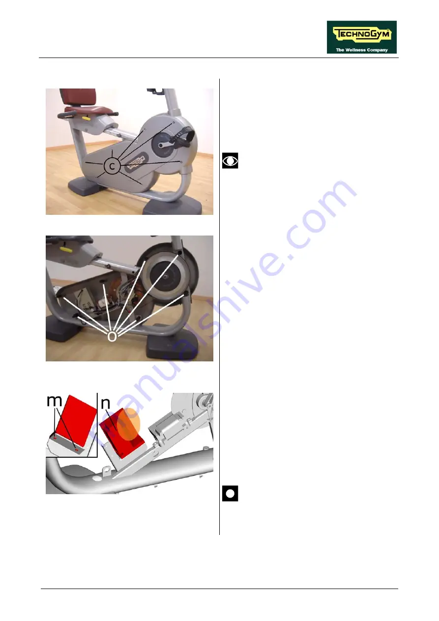
7. On the right side, back off the 7 screws
c
using a 4-mm he
8
This operation may be awkward. If in
difficulty, perform the standard
procedure which involves disassembling
the right pedal crank and then removing
the right guard.
Figure 4.5-2
10.
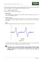
9. Remove the seven pins rom
o
the left guard.
Remove the left guard.
Figure 4.5-3
11.
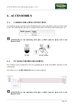
Unplug the connectors indicated in the
figure.
12. Back off the two screws
p
using a 4-mm
allen-T wrench.
13. Remove the brake board
n
.
14. Assemble the brake board
12
, included in the
kit.
15.
Connect all the connectors previously
disconnected from the brake board.
During assembly, lock down the screws
“m” using a torque wrench set for 5 Nm.
Continued on following page
→
Page 4.7
Summary of Contents for Recline 500
Page 1: ...SERVICE MAINTENANCE MANUAL REV 2 4...
Page 2: ......
Page 4: ......
Page 10: ...RECLINE EXCITE Service Maintenance Manual rev 2 4 Page vi Page intentionally left blank...
Page 46: ...RECLINE EXCITE Service Maintenance Manual rev 2 4 Page 3 14 Page intentionally left blank...
Page 58: ...RECLINE EXCITE Service Maintenance Manual rev 2 4 Page 4 12 Page intentionally left blank...
Page 94: ...RECLINE EXCITE Service Maintenance Manual rev 2 4 Page 6 34 Page intentionally left blank...
Page 134: ...RECLINE EXCITE Service Maintenance Manual rev 2 4 Page 7 40 Page intentionally left blank...
Page 140: ...RECLINE EXCITE Service Maintenance Manual rev 2 4 Page 8 6 Page intentionally left blank...
Page 172: ...RECLINE EXCITE Service Maintenance Manual rev 2 4 Page 9 32 Page intentionally left blank...
Page 181: ......


