RUN 600 XTPRO: Service & Maintenance Manual - rev. 1.3
Page 7.34
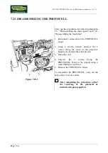
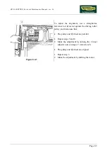
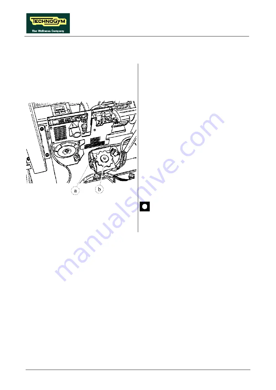
7.22. DISASSEMBLING THE PHOTOCELL
Figure 7.22-1
Carry out the procedures described in paragraphs
7.9. “Disassembling the motor guard” and 7.10.
“Disassembling the front plate”.
1. Disconnect connector
a
on the PHOTOCELL
board.
2. Using a 10-mm wrench, unscrew the 2
screws fixing the cover of the protective
housing of encoder wheel
b
if present.
3. Open the cover.
4.
Unscrew the 2 screws fixing the
PHOTOCELL board to the support using a
small Phillips screwdriver.
5. Remove the PHOTOCELL board.
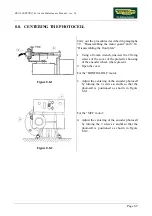
To reassemble the PHOTOCELL, carry out the
above steps in reverse order.
After completing the procedure, adjust
the centering of the photocell as
instructed in paragraph 8.8. .
Summary of Contents for RUN 600 XTPRO
Page 1: ...SERVICE MAINTENANCE MANUAL REV 1 3...
Page 2: ......
Page 4: ......
Page 24: ...RUN 600 XTPRO Service Maintenance Manual rev 1 3 Page 2 14 Page intentionally left blank...
Page 36: ...RUN 600 XTPRO Service Maintenance Manual rev 1 3 Page 3 12 Page intentionally left blank...
Page 38: ...RUN 600 XTPRO Service Maintenance Manual rev 1 3 Page 4 2 Page intentionally left blank...
Page 82: ...RUN 600 XTPRO Service Maintenance Manual rev 1 3 Page 6 42 Page intentionally left blank...
Page 126: ...RUN 600 XTPRO Service Maintenance Manual rev 1 3 Page 8 10 Page intentionally left blank...
Page 156: ...RUN 600 XTPRO Service Maintenance Manual rev 1 3 Page 11 14 Page intentionally left blank...
Page 157: ......

