RUN 600 XTPRO: Service & Maintenance Manual - rev. 1.3
Page 2.4
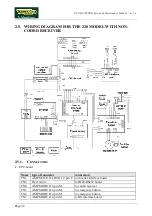
2.5.2. W
IRING
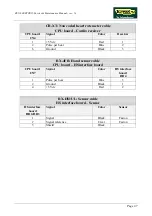
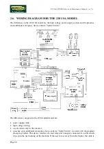
The high voltage power supply cables and the ground connections are not described here, in that
they can be easily determined from the wiring diagram above.
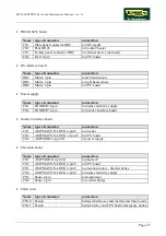
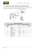
RXIMQ-1: Internal connection cable
CPU board – Inverter interface board – Elevation board
CPU board
CN1
Signal
Color
Inverter
interface
board
CN2
Elevation
board
CN2
1
+12 Vdc
Blue 1
1
-
2
+5 Vdc
Brown 1
2
-
3 Ground
Gray
1 3
-
4 -12
Vdc
White 5
-
5 not
used
Violet 12
-
6
Tread belt speed
reference (PWM)
Red 10
-
7 Start
Black 8
-
8 Inverter
alarm
Orange 9
-
9 Status
Brown
2 -
1
10 Up
Pink
-
2
11 Down
Blue
2 -
3
12 Ground
Gray
2 -
4
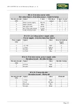
RX-5/A bis: Inverter cable
Inverter interface board – Inverter – Patch cord
Inverter interface
board
CN1
Signal
Color
Inverter Patch
cord
CN10
- Thermal
cutout
Green
3
2
1 White
-
-
Thermal cutout Gnd
White P24
1
2 Start
Grey 1 -
3 Alarm
Blue
AL1
-
4 Alarm
Gnd
Red
AL0
-
5
Speed analogue reference (0-10
Vdc)
Brown O -
6
Speed Gnd
Black
L
-
Summary of Contents for RUN 600 XTPRO
Page 1: ...SERVICE MAINTENANCE MANUAL REV 1 3...
Page 2: ......
Page 4: ......
Page 24: ...RUN 600 XTPRO Service Maintenance Manual rev 1 3 Page 2 14 Page intentionally left blank...
Page 36: ...RUN 600 XTPRO Service Maintenance Manual rev 1 3 Page 3 12 Page intentionally left blank...
Page 38: ...RUN 600 XTPRO Service Maintenance Manual rev 1 3 Page 4 2 Page intentionally left blank...
Page 82: ...RUN 600 XTPRO Service Maintenance Manual rev 1 3 Page 6 42 Page intentionally left blank...
Page 126: ...RUN 600 XTPRO Service Maintenance Manual rev 1 3 Page 8 10 Page intentionally left blank...
Page 156: ...RUN 600 XTPRO Service Maintenance Manual rev 1 3 Page 11 14 Page intentionally left blank...
Page 157: ......


