RUN 600 XTPRO: Service & Maintenance Manual - rev. 1.3
Page 3.3
amplitude of approximately 30 msec) each time a heart beat is detected.
There are 3 jumpers on this circuit board, which must be configured as indicated in the table below:
Jumper Configuration
JP1 Open
JP2 Closed
JP3 Closed
3.1.5. RJ45-RS232
BOARD
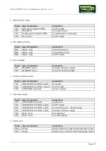
This circuit board provides the machine connections to external devices:
•
1 serial port for connecting to the TGS reader;
•
1 serial port, currently not used, for future connections;
•
1 RJ45 port for the power supply to the portable Cardio Theater unit.
3.1.6. P
OWER SUPPLY
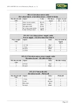
Receives the mains voltage at its input and outputs the DC voltages (+5 Vdc, +12 Vdc and
−
12
Vdc) which supply the display and the inverter interface board.
3.1.7. B
ELT MOTOR
An asynchronous three-phase motor which, by means of a pulley and a poly-v belt, turns the driving
roller of the tread belt. Each motor phase is equipped with a normally-closed bimetallic safety which
opens when the temperature exceeds a preset threshold, in order to safeguard the integrity of the
motor. The 3 bimetallic safeties are connected in series and reach the inverter as a NC external input
signal. When this contact opens, the inverter generates an alarm.
When the new emergency button has been introduced, the flywheel has been modified too. It is
bigger in order to have a smoother slow down when the emergency button has been pressed or when
the power supply goes off.
The belt motor has a power of 1.5 KW (2 Hp).
3.1.8. I
NVERTER
This is the device which supplies the three-phase belt motor. It receives a DC reference voltage
from the inverter interface board. Variations in this voltage cause corresponding variations in the
VAC frequency produced by the inverter, in the rotation speed of the motor, and hence change the
speed of the tread belt. It handles motor drive errors and, in the event of an error, shuts down the
power supply to the motor and sends an alarm signal through the interface board to the display. The
event which caused the error is memorized as an error code.
The inverter power supply is enabled by the relay activated by the emergency button. When the
button is pressed, the relay contact opens, the power to the inverter goes off and hence the belt
motor stops.
The following inverter models are used on these machines:
Summary of Contents for RUN 600 XTPRO
Page 1: ...SERVICE MAINTENANCE MANUAL REV 1 3...
Page 2: ......
Page 4: ......
Page 24: ...RUN 600 XTPRO Service Maintenance Manual rev 1 3 Page 2 14 Page intentionally left blank...
Page 36: ...RUN 600 XTPRO Service Maintenance Manual rev 1 3 Page 3 12 Page intentionally left blank...
Page 38: ...RUN 600 XTPRO Service Maintenance Manual rev 1 3 Page 4 2 Page intentionally left blank...
Page 82: ...RUN 600 XTPRO Service Maintenance Manual rev 1 3 Page 6 42 Page intentionally left blank...
Page 126: ...RUN 600 XTPRO Service Maintenance Manual rev 1 3 Page 8 10 Page intentionally left blank...
Page 156: ...RUN 600 XTPRO Service Maintenance Manual rev 1 3 Page 11 14 Page intentionally left blank...
Page 157: ......

