RUN 600 XTPRO: Service & Maintenance Manual - rev. 1.3
Page 3.6
3.2. TREAD-BELT MOTOR DRIVE
3.2.1. M
ECHANICS
The tread belt is actuated by the motor through a linkage consisting of the motor pulley, the driving
roller and the belt which connects them. In this way, a given belt motor speed corresponds to a
predetermined linear tread belt speed. The belt motor is controlled by the inverter which generates a
variable-frequency sine wave signal: variations in frequency cause the motor speed and hence the
tread belt speed to vary.
3.2.2. C
ONTROLS
To start the motor, the CPU board sends the inverter a Start signal through the inverter interface
board, enabling the inverter to drive the motor. After outputting this enable signal, the CPU board
sets the motor speed by sending a PWM signal to the inverter interface board, which the inverter
interface board converts into an analog input voltage to the inverter. The relationship between the
analog input voltage and the inverter output frequency is determined by the values of the
configuration parameters in the inverter program.
During its movement, the inverter checks the motor and, if any problems are detected (overvoltage,
overcurrent, SW and HW problems to the inverter, etc.) it halts the motor and sends an alarm signal
to the CPU board, which displays the error message
•
CAUTION = E3
if the alarm signal is sent at the belt start;
•
CAUTION = E4
if the alarm signal is sent during the belt movement.
To protect the motor from overheating, each motor phase has a thermal cutout connected in series. If
the temperature exceeds the threshold value, the thermal cutout opens and interrupts the circuit. The
inverter detects this condition as the opening of a NC external contact. In such a case the inverter
halts the motor and outputs an alarm signal to the CPU board, which displays the error message
cited above.
3.2.3. T
HE SIGNALS INVOLVED
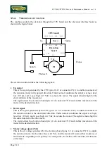
The machine controls the speed of the belt motor by means of the CPU board and the inverter
interface board, as shown in the following figure:
Summary of Contents for RUN 600 XTPRO
Page 1: ...SERVICE MAINTENANCE MANUAL REV 1 3...
Page 2: ......
Page 4: ......
Page 24: ...RUN 600 XTPRO Service Maintenance Manual rev 1 3 Page 2 14 Page intentionally left blank...
Page 36: ...RUN 600 XTPRO Service Maintenance Manual rev 1 3 Page 3 12 Page intentionally left blank...
Page 38: ...RUN 600 XTPRO Service Maintenance Manual rev 1 3 Page 4 2 Page intentionally left blank...
Page 82: ...RUN 600 XTPRO Service Maintenance Manual rev 1 3 Page 6 42 Page intentionally left blank...
Page 126: ...RUN 600 XTPRO Service Maintenance Manual rev 1 3 Page 8 10 Page intentionally left blank...
Page 156: ...RUN 600 XTPRO Service Maintenance Manual rev 1 3 Page 11 14 Page intentionally left blank...
Page 157: ......


