RUN 600 XTPRO: Service & Maintenance Manual - rev. 1.3
Page 3.11
•
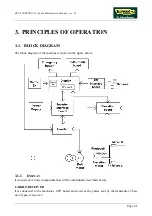
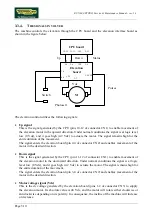
Pulse signal
This is a square wave signal, alternating between logic level low (0 Vdc) and logic level high (5
Vdc), generated by the photocell in response to movements of the elevation motor. Each pulse
corresponds to a slot of the encoder wheel, which is incorporated into and moves with the motor
itself. The signal enters the elevation board (pin 2-4 of connector CN1) and is used by the
elevation board for controlling the movement.
The photocell also outputs a direction signal, which varies from logic level high (5 Vdc) to low
(0 Vdc) depending on whether the motor is moving in a clockwise or anticlockwise direction.
This signal is input to the elevation board (pin 3-4 of connector CN1).
To operate correctly, the photocell requires a 5 Vdc supply voltage which is provided by the
elevation board (pins 1-4 of connector CN1).
•
Status signal
This is the square wave signal generated by the elevation board (pin 1-4 of connector CN2) that
changes its logic level (level low 0 Vdc and level high 5 Vdc) whenever the elevation board
receives from the photocell a number of pulses corresponding to an 0.5% variation in the
elevation.
The CPU board receives this signal (pin 9-12 of connector CN1) which indicates the actual
elevation of the machine. Comparing it with the desired elevation value, the CPU determines
whether to keep the Up or Down signal asserted to continue the movement or, if the desired
elevation has been reached, to reset the Up or Down signal.
•
Limit switch signal
This is the signal from the 2 limit switches which determine the machine’s range of elevation
motion. The lower microswitch is a NC contact input to the elevation board (pin 4-6 of
connector CN3). When this contact opens the circuit board inhibits movement in the down
direction. The upper microswitch is a NO contact input to the elevation board (pin 3-6 of
connector CN3). The upper microswitch is always pressed therefore it provides a NC contact.
When this contact opens the circuit board inhibits movement in the up direction.
Summary of Contents for RUN 600 XTPRO
Page 1: ...SERVICE MAINTENANCE MANUAL REV 1 3...
Page 2: ......
Page 4: ......
Page 24: ...RUN 600 XTPRO Service Maintenance Manual rev 1 3 Page 2 14 Page intentionally left blank...
Page 36: ...RUN 600 XTPRO Service Maintenance Manual rev 1 3 Page 3 12 Page intentionally left blank...
Page 38: ...RUN 600 XTPRO Service Maintenance Manual rev 1 3 Page 4 2 Page intentionally left blank...
Page 82: ...RUN 600 XTPRO Service Maintenance Manual rev 1 3 Page 6 42 Page intentionally left blank...
Page 126: ...RUN 600 XTPRO Service Maintenance Manual rev 1 3 Page 8 10 Page intentionally left blank...
Page 156: ...RUN 600 XTPRO Service Maintenance Manual rev 1 3 Page 11 14 Page intentionally left blank...
Page 157: ......


