RUN 600 XTPRO: Service & Maintenance Manual - rev. 1.3
Page 6.32
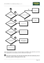
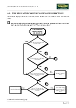
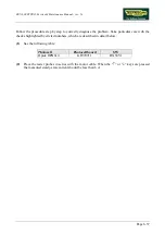
If you need to replace the elevation board, reassemble on the new board the chip
installed into the old one, if it is a different version.
(1)
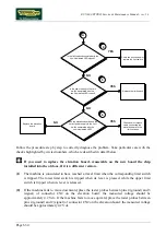
Place the tester probes between pins 1 and 2 of connector CN3 on the elevation board. When
the “
↑
” or “
↓
” key is pressed the measured value should be approximately 48 Vdc.
(2)
Place the tester probes between pins 12 (ground) and 11 (signal) of connector CN1 on the
CPU board. When the “
↓
” key is pressed the measured value should be approximately 4.2
Vdc. Place the tester probes between pins 12 (ground) and 10 (signal) of connector CN1 of the
CPU board. When the “
↑
” key is pressed the measured voltage should be approximately 4.2
Vdc.
(3)
Place the tester probes between pins 4 (ground) and 3 (signal) of connector CN2 on the
elevation. board. When the “
↓
” key is pressed the measured voltage should be approximately
4.2 Vdc. Place the tester probes between pins 4 (ground) and 2 (signal) of connector CN2 on
the elevation board. When the “
↑
” key is pressed the measured voltage should be
approximately 4.2 Vdc.
(4)
Place the tester probes between pins 1 and 2 of connector CN4 on the elevation board. The
measured voltage should be approximately 220 VAC or 110 VAC depending on the type of
mains electricity supply.
(5)
Place the tester probes between pins 1 and 2 of connector CN6 on the elevation board. The
measured voltage should be approximately 50 Vdc.
(6)
Disconnect the yellow transformer cables on the rectifier bridge and place the tester probes
across the 2 terminals. The measured voltage should be 38 VAC.
(7)
Place the tester probes in series with the motor cable. When the “
↑
” or “
↓
” key is pressed the
measured steady-state current should be less than 6 A.
(8)
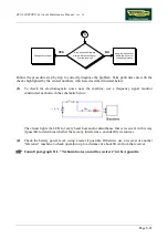
Slightly lift the connector on the photocell and place the scope probes between pins 4
(ground) and 2 (signal). When the motor moves, the tester should detect the pulses generated
by the photocell.
(9)
Place the tester probes between pins 4 (ground) and 1 (signal) of connector CN2 on the
elevation. board. When the motor moves, there should be a level changing for each 0.5%
change in the machine elevation.
(10)
As for step (11), but with the tester probes between pins 12 (ground) and 9 (signal) of
connector CN1 on the CPU board.
Summary of Contents for RUN 600 XTPRO
Page 1: ...SERVICE MAINTENANCE MANUAL REV 1 3...
Page 2: ......
Page 4: ......
Page 24: ...RUN 600 XTPRO Service Maintenance Manual rev 1 3 Page 2 14 Page intentionally left blank...
Page 36: ...RUN 600 XTPRO Service Maintenance Manual rev 1 3 Page 3 12 Page intentionally left blank...
Page 38: ...RUN 600 XTPRO Service Maintenance Manual rev 1 3 Page 4 2 Page intentionally left blank...
Page 82: ...RUN 600 XTPRO Service Maintenance Manual rev 1 3 Page 6 42 Page intentionally left blank...
Page 126: ...RUN 600 XTPRO Service Maintenance Manual rev 1 3 Page 8 10 Page intentionally left blank...
Page 156: ...RUN 600 XTPRO Service Maintenance Manual rev 1 3 Page 11 14 Page intentionally left blank...
Page 157: ......


