RUN 600 XTPRO: Service & Maintenance Manual - rev. 1.3
Page 7.1
7. DISASSEMBLY OF COMPONENTS
7.1. DISASSEMBLING THE DISPLAY
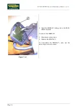
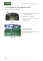
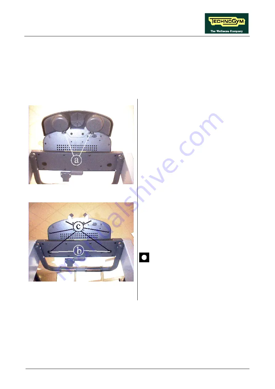
Figure 7.1-1
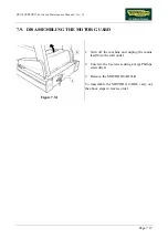
1. Turn off the machine and unplug the mains
lead from the wall output.
2. Unscrew the 2 screws
a
using a large Phillips
screwdriver.
3. Remove the tidy rack.
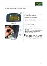
Figure 7.1-2
4. Remove the 2 caps
b
.
5. Unscrew the 6 screws
c
, using a large
Phillips screwdriver.
Support the DISPLAY before removing
the last screw.
Continued on the following page
→
Summary of Contents for RUN 600 XTPRO
Page 1: ...SERVICE MAINTENANCE MANUAL REV 1 3...
Page 2: ......
Page 4: ......
Page 24: ...RUN 600 XTPRO Service Maintenance Manual rev 1 3 Page 2 14 Page intentionally left blank...
Page 36: ...RUN 600 XTPRO Service Maintenance Manual rev 1 3 Page 3 12 Page intentionally left blank...
Page 38: ...RUN 600 XTPRO Service Maintenance Manual rev 1 3 Page 4 2 Page intentionally left blank...
Page 82: ...RUN 600 XTPRO Service Maintenance Manual rev 1 3 Page 6 42 Page intentionally left blank...
Page 126: ...RUN 600 XTPRO Service Maintenance Manual rev 1 3 Page 8 10 Page intentionally left blank...
Page 156: ...RUN 600 XTPRO Service Maintenance Manual rev 1 3 Page 11 14 Page intentionally left blank...
Page 157: ......

