RUN 600 XTPRO: Service & Maintenance Manual - rev. 1.3
Page 7.17
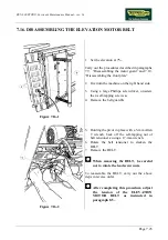
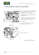
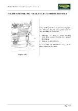
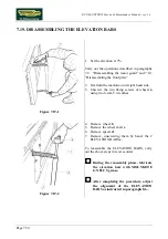
7.12. DISASSEMBLING THE DRIVEN ROLLER, THE DRIVING
ROLLER, THE TREAD BELT AND THE MOTOR BELT
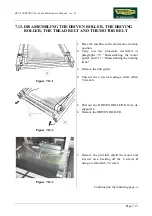
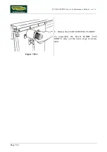
Figure 7.12-1
1. Place the machine in the maximum elevation
position.
2. Carry out the procedure described in
paragraphs 7.9. “Disassembling the motor
guard” and 7.11. “Disassembling the running
track”.
3. Remove the dust guard.
4. Unscrew the 2 screws
a
using a 6-mm Allen
T wrench.
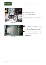
Figure 7.12-2
5. Pull out the DRIVEN ROLLER
b
from its
supports
c
.
6. Remove the DRIVEN ROLLER.
Figure 7.12-3
7. Remove the grid that shield the motor and
inverter area, backing off the 4 screws
d
using a 4-mm Allen T wrench.
Continued on the following page
→
Summary of Contents for RUN 600 XTPRO
Page 1: ...SERVICE MAINTENANCE MANUAL REV 1 3...
Page 2: ......
Page 4: ......
Page 24: ...RUN 600 XTPRO Service Maintenance Manual rev 1 3 Page 2 14 Page intentionally left blank...
Page 36: ...RUN 600 XTPRO Service Maintenance Manual rev 1 3 Page 3 12 Page intentionally left blank...
Page 38: ...RUN 600 XTPRO Service Maintenance Manual rev 1 3 Page 4 2 Page intentionally left blank...
Page 82: ...RUN 600 XTPRO Service Maintenance Manual rev 1 3 Page 6 42 Page intentionally left blank...
Page 126: ...RUN 600 XTPRO Service Maintenance Manual rev 1 3 Page 8 10 Page intentionally left blank...
Page 156: ...RUN 600 XTPRO Service Maintenance Manual rev 1 3 Page 11 14 Page intentionally left blank...
Page 157: ......

