background image

RUN 600 XTPRO: Service & Maintenance Manual - rev. 1.3 


Page 9.3 

 
and press 

ENTER

 to confirm your choice. 

9.1.6.   E

NABLING THE 

“ENTER” 

KEY


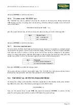
The “ENTER” key can be enabled to increase the amount of exercising time during manual and 
CPR training sessions. To change the current setting, when the setting is actually in use will scroll 
on the LED matrix: 
 

ENTER TO INCREASE TIME = xxx 

 
press the proper numeric key (

1

 or 

2

) to choose the desired setting, as for the following table: 


K

EY


“E

NTER

” 

KEY


OFF = DISABLED 

ON = ENABLED 

 
and press 

ENTER

 to confirm your choice. 

9.1.7.   S

ETTING THE PRIORITY


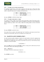
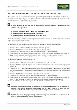
For cases where both the chest band and hand sensor are present, it is possible to configure which 
one should be the priority source for the heart rate display. Obviously, if there is a signal available 
from only one of the 2 sources, it will be used even if it has not been configured as the priority 
source. To change this setting, when the LED display is showing the current priority value, press the 
number keys (from 

1

 to 

2

) to set the desired priority as shown in the following table: 


K

EY


P

RIORITY


CHEST BAND PRIORITY 

HEART SENSOR PRIORITY 

 
then press 

ENTER

 to confirm the changes made. 

 
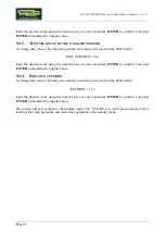
The system will now go back to the standby mode. The “CLEAR” key can be pressed at any time to 
interrupt the setup procedure and return the equipment to the standby mode. 

9.2.   TECHNICAL SETTING PARAMETERS 

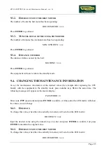
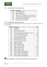
To change the settings of the machine, when the equipment is in the standby mode, press numeric 
keys 

314

 at the same time. The following will appear on the LED matrix: 


PASSWORD = 0 

 
Now, use the numeric keys to enter 

2501

 (the password) and press 

ENTER

 to confirm. At this 

point, the setting procedure will show on the LED matrix the actual settings. 

Summary of Contents for RUN 600 XTPRO

Page 1: ...SERVICE MAINTENANCE MANUAL REV 1 3...

Page 2: ......

Page 3: ...THE MACHINE IS TURNED OFF NOTE The information contained in this document is subject to change without notice Technogym does not guarantee this documentation in any way Technogym shall not be held res...

Page 4: ......

Page 5: ...GRAM WITH ZT30 POWER SUPPLY 2 13 3 PRINCIPLES OF OPERATION 3 1 3 1 BLOCK DIAGRAM 3 1 3 1 1 Display 3 1 3 1 2 Emergency button 3 2 3 1 3 Cardio transmitter 3 2 3 1 4 HS interface board 3 2 3 1 5 RJ45 R...

Page 6: ...7 1 7 1 DISASSEMBLING THE DISPLAY 7 1 7 2 DISASSEMBLING THE EPROM 7 3 7 3 DISASSEMBLING THE CPU BOARD 7 4 7 4 DISASSEMBLING THE KEYBOARD 7 5 7 5 DISASSEMBLING THE CARDIO RECEIVER 7 6 7 6 DISASSEMBLING...

Page 7: ...1 Setting up the operation 10 1 10 1 2 Cleaning operations 10 1 10 1 3 Lubricating the tread belt 10 1 10 2 ROUTINE MAINTENANCE OPERATIONS 10 2 10 2 1 Internal cleaning operations 10 2 10 2 2 Lubrica...

Page 8: ...SONAL CODED DEVICE 11 7 11 2 1 Operating modes 11 7 11 3 HITACHI SJ100 INVERTER ERROR CODES 11 9 11 4 PROCEDURE FOR CLEARING THE ERROR MEMORY ON HITACHI SJ100 INVERTER 11 10 11 5 PROCEDURE FOR CLEARIN...

Page 9: ...non observance may cause damage to the machine Information about the operation in progress OBSERVE observation about the operation in progress 1 2 RECOMMENDATIONS Technogym recommends the following st...

Page 10: ...recommended brands 3 Use special tools where specified 4 Consult the Technical Newsletters which may contain more up to date information on adjustments and maintenance than those contained in this ma...

Page 11: ...ragraph 2 7 110 Model 220 and 220 USA Models Mains voltage 115 VAC 230 VAC Frequency 50 60 Hz 50 60 Hz Consumption 1800 Watt 16 A 1800 Watt 8 A Fuse 5x20 4 A fast blow 5x20 4 A fast blow 2 3 AMBIENT S...

Page 12: ...CONNECTORS CPU board Name type of connector connection CN1 AMP MATE N LOCK 12 pin F to inverter interface board CN2 Flat 10 pin to RJ45 RS232 board CN4 AMP MODU II 6 pin M to cardio receiver CN5 AMP M...

Page 13: ...ity supply CN2 PANDUIT 8 pin to inverter interface board Inverter interface board Name type of connector connection CN1 AMP MATE N LOCK 6 pin F to inverter CN2 AMP MATE N LOCK 12 pin F to CPU board CN...

Page 14: ...ion board CN2 1 12 Vdc Blue 1 1 2 5 Vdc Brown 1 2 3 Ground Gray 1 3 4 12 Vdc White 5 5 not used Violet 12 6 Tread belt speed reference PWM Red 10 7 Start Black 8 8 Inverter alarm Orange 9 9 Status Bro...

Page 15: ...round Black 1 1 RX 8 Low voltage power supply cable Power supply Inverter interface board Power supply CN2 Signal Color Inverter interface board CN4 1 12 Vdc Red 2 3 5 Vdc Yellow 4 4 Ground Black 3 6...

Page 16: ...cord CN11 1 Reference Brown 1 2 Brown 2 Relay power supply 12 Vdc Blue 4 0 RX 1Q Relay cable Patch cord Relay Patch cord CN11 Signal Color Relay 1 Relay power supply 12 Vdc Blue 1 2 Reference Brown 0...

Page 17: ...ed 1 2 Pulse per beat Blue 2 6 Ground Black 3 RX 4FR Hand sensor cable CPU board HS interface board CPU board CN7 Signal Color HS interface board HD4 1 Pulse per beat Blue 3 2 Ground Black 1 4 5 Vdc R...

Page 18: ...d a Safety Switch The differences compared to the 220 standard model are power supply cable high voltage wiring use of a filter only for the inverter presence of an additional emergency device called...

Page 19: ...he safety switch requires cable RXIMQ 13S to be modified as follows RX 13USA Emergency cable CPU Emergency button Safety switch CPU board CN6 Signal Color Emergency button Safety switch 1 NC contact B...

Page 20: ...ker which receives the 110 VAC input and generates the 220 VAC output From this point onward the machine wiring diagram is the same as for the 220 version The differences compared to the 220 USA model...

Page 21: ...y difference compared to the model with non coded receiver is the NSC XT cable between the CPU board and the coded receiver which is described below NSC XT Non coded heart rate meter cable CPU board C...

Page 22: ...motor and to the inverter interface board as illustrated below RX 5 Inverter cable Inverter interface board Inverter Motor thermal cutout Inverter interface board CN1 Signal Color Inverter Motor ther...

Page 23: ...model with SWT40 power supply lies in the power supply itself and its connection to the inverter interface board as illustrated below RX 8 Low voltage power supply cable Power supply Inverter interfa...

Page 24: ...RUN 600 XTPRO Service Maintenance Manual rev 1 3 Page 2 14 Page intentionally left blank...

Page 25: ...IAGRAM The block diagram of the machine is shown in the figure below 3 1 1 DISPLAY It consists of various components that will be individually described below CARDIO RECEIVER It is connected to the ma...

Page 26: ...from the machine with SN 02000549 it consists of a new maintained button which needs to be released after it has been pressed The button which has a NC contact is connected both to the CPU board and t...

Page 27: ...The 3 bimetallic safeties are connected in series and reach the inverter as a NC external input signal When this contact opens the inverter generates an alarm When the new emergency button has been in...

Page 28: ...on the direction of rotation 3 1 11 PHOTOCELL This is the device which provides feedback on the motion of the elevation motor It transmits one pulse for each tooth detected on the encoder wheel which...

Page 29: ...OSWITCH There are 2 limit switches which control the range of motion of the elevation mechanism These switches are positioned at the travel limits of the elevation bars and change state when pressed a...

Page 30: ...relationship between the analog input voltage and the inverter output frequency is determined by the values of the configuration parameters in the inverter program During its movement the inverter che...

Page 31: ...gnal generated by the CPU pins 6 3 of connector CN1 to control the motor speed It is a PWM signal that is to say a fixed frequency square wave with a variable duty cycle The logic of this control has...

Page 32: ...inverter is programmed to expect a NC signal on these pins When at least one thermal cutout is triggered the contact opens and the inverter detecting the open circuit condition generates an alarm sign...

Page 33: ...established 0 0 incline position 3 3 3 CONTROLS To vary the incline the CPU board sends the elevation board an Up signal move motor in the up direction to increase the elevation or a Down signal move...

Page 34: ...n Down signal This is the signal generated by the CPU pin 11 12 of connector CN1 to enable movement of the elevation motor in the downward direction Under normal conditions the signal is at logic leve...

Page 35: ...enerated by the elevation board pin 1 4 of connector CN2 that changes its logic level level low 0 Vdc and level high 5 Vdc whenever the elevation board receives from the photocell a number of pulses c...

Page 36: ...RUN 600 XTPRO Service Maintenance Manual rev 1 3 Page 3 12 Page intentionally left blank...

Page 37: ...ble Control panel Retrofit Control panel DB9 male Signal Color Retrofit 1 12 Vdc Yellow 8 5 Ground Green 6 3 Rx Brown 2 2 Tx White 1 For all further information including troubleshooting refer to the...

Page 38: ...RUN 600 XTPRO Service Maintenance Manual rev 1 3 Page 4 2 Page intentionally left blank...

Page 39: ...the machine and have a rating of at least 1800 Watt 9 Do not connect other machines or users to the same wall outlet 10 Position the mains lead of the machine where is will not be underfoot For this...

Page 40: ...s standby mode awaiting a keyboard command To check the correct operation of the machine get on the machine press the Start key on the keyboard to begin exercising check that the belt motor starts pre...

Page 41: ...onse This type of box is a step in the troubleshooting procedure where an ACTION must be carried out It typically contains a description of the ACTION necessary to resolve the problem Therefore after...

Page 42: ...reach the control panel Is the fuse OK Is mains lead OK Does the wall output supply the correct voltage Replace the blown fuse Replace the mains lead Connect machine to a suitable electrical output TH...

Page 43: ...e output of the inverter interface board Replace the CPU board Replace cable connecting the power supply to the inverter interface board Replace the inverter interface board Replace cable connecting t...

Page 44: ...e automatic circuit breaker NO Is the mains voltage present at the output of the automatic circuit breaker 8 NO Replace the automatic circuit breaker YES Is the mains voltage present at the input to t...

Page 45: ...e 220 model with non coded receiver 3 As for point 2 but on connector CN1 of the CPU board 4 As for point 2 but on connector CN4 of the inverter interface board 5 As for point 2 but on connector CN2 o...

Page 46: ...R IS OFF Is the emergency button pressed Is the v oltage at the output of the CPU board correct Replace the CPU board Correct operation YES NO NO 1 Is the voltage at the CN11 patch connector correct R...

Page 47: ...orrectly diagnose the problem Take particular care with the checks highlighted by circled numbers which are described in detail below 1 Place the tester probes between pins 1 and 3 of the CPU board Th...

Page 48: ...minals correct Replace the emergency button Correct operation YES NO NO YES 1 Is the voltage at the output of the CPU board correct Replace cable between the CPU board and the emergency button Replace...

Page 49: ...ing the training session The most common causes are principally One of the motor thermal cutouts has been tripped The inverter has shut down for protection from a mains voltage fluctuation spike or gl...

Page 50: ...Check the error message displayed and or memorized by the inverter E01 E02 E03 E04 E05 E06 E07 E08 E10 E11 E22 E09 E12 E14 E15 E21 None The inv erter is on YES NO Execute the procedure The inv erter...

Page 51: ...a good state and lubricated NO Follow the procedure step by step to correctly diagnose the problem Take particular care with the checks highlighted by circled numbers which are described in detail bel...

Page 52: ...able interference The machine is OK Replace the inverter NO NO E07 E06 Follow the procedure step by step to correctly diagnose the problem Take particular care with the checks highlighted by circled n...

Page 53: ...he machine is OK Replace the inverter NO YES E10 E08 E11 Follow the procedure step by step to correctly diagnose the problem Take particular care with the checks highlighted by circled numbers which a...

Page 54: ...automatic circuit breaker and filter NO 3 Is the supply voltage at the filter output correct NO Replace the filter YES Check and reinstate the wiring between the filter and inverter YES Follow the pro...

Page 55: ...220 VAC or 110 VAC depending on the type of mains electricity supply This error may be generated even by brief drops in the line voltage due to overloads or other causes Therefore it can be very usef...

Page 56: ...e inverter input Replace the inverter Programming error on the inverter Reprogram it NO YES Follow the procedure step by step to correctly diagnose the problem Take particular care with the checks hig...

Page 57: ...ses isolated from ground at the inverter output Replace the inverter NO 1 Follow the procedure step by step to correctly diagnose the problem Take particular care with the checks highlighted by circle...

Page 58: ...circuit breaker and the filter NO 3 Is the supply voltage at the output of the filter correct NO Replace the filter YES Check and reinstate cable between the filter and the inveter YES Follow the pro...

Page 59: ...220 VAC or 110 VAC depending on the type of mains electricity supply This error may be generated even by brief drops in the line voltage due to overloads or other causes Therefore it can be very usef...

Page 60: ...RTER DISPLAY SHOWS E21 This inverter error message is associated with problems of high inverter temperature YES Replace the inverter E21 Does the machine resume correct operation after being switched...

Page 61: ...he input to the inverter interface board Check and or replace cable connecting the inverter interface board to the inverter Replace the inverter interface board NO NO YES Is the alarm present at the i...

Page 62: ...the inverter interface board 3 Place the tester probes between pins 3 ground and 9 signal of connector CN2 on the inverter interface board Under an alarm condition the measured voltage should be 0 Vd...

Page 63: ...windings short circuited or open circuited YES Replace the inverter 1 NO Replace the belt motor Follow the procedure step by step to correctly diagnose the problem Take particular care with the checks...

Page 64: ...measured voltage should be 4 8 Vdc To check the PWM signal place a tester between pins 6 signal and 3 ground of connector CN1 on the CPU board When the belt is halted the measured voltage should be 5...

Page 65: ...RUN 600 XTPRO Service Maintenance Manual rev 1 3 Page 6 25 speed The variation of the signal must be accompanied by a corresponding variation in the belt speed see Table 6 7 1 or Table 6 7 2...

Page 66: ...motor group THE DISPLAYED SPEED IS INCORRECT Is the relationship between the displayed speed and the inverter frequency correct Is the inverter control voltage correct YES NO YES Replace the inverter...

Page 67: ...between the inverter interface board and the inverter YES NO 5 Is the inverter control voltage at the output of the inverter interface board correct Follow the procedure step by step to correctly dia...

Page 68: ...will be slightly different but still comparable 4 Place the tester probes between the terminals O signal and L ground of the inverter Check that during machine operation the speed shown on the displa...

Page 69: ...ON E5 Check the status of the 2 LEDs on the elevation board Is the supply to the elevation motor correct when the actuation command arrives BOTH OFF BOTH ON YES 1 A Does the elevation board receive th...

Page 70: ...or replace the cable connecting the elevation board to the filter YES Does the voltage at output by the transformer rectifier reach the elevation board NO Replace the elevation board YES Is the volta...

Page 71: ...ard YES Is the pulse signal at the photocell output correct 9 10 Does the status signal reach the CPU board Replace the CPU board 7 NO Check and or replace cable between CPU board and elevation board...

Page 72: ...ed the measured voltage should be approximately 4 2 Vdc 4 Place the tester probes between pins 1 and 2 of connector CN4 on the elevation board The measured voltage should be approximately 220 VAC or 1...

Page 73: ...3 3 2 The reset procedure THE ELEVATION MOVES IN ONLY ONE DIRECTION Are 2 LEDs on the elevation board both illuminated Is the machine in one of the 2 travel limit positions YES NO YES 1 2 Does the el...

Page 74: ...with the checks highlighted by circled numbers which are described in detail below If you need to replace the elevation board reassemble on the new board the chip installed into the old one if it is a...

Page 75: ...c 4 DL1 corresponds to the upper limit switch while DL2 on SMD board DL3 on traditional board corresponds to the lower limit switch 5 Disconnect the 2 connecting cables of the relevant limit switch an...

Page 76: ...es as a result of excessively high currents THE DISPLAYED ELEVATION IS INCORRECT Is the position of the limit switch correct Is the elevation motor current correct YES NO YES Lubricate the elevation b...

Page 77: ...ke particular care with the checks highlighted by circled numbers which are described in detail below 1 See the following table Photocell Photocell board SW Optek OPB610 GF970711 RX50V1 2 Place the te...

Page 78: ...step by step to correctly diagnose the problem Take particular care with the checks highlighted by circled numbers which are described in detail below 1 Place the tester probes between pins 1 and 3 c...

Page 79: ...HS interface board Replace the HS interface board 2 YES NO THERE IS NO HEART RATE SIGNAL Follow the procedure step by step to correctly diagnose the problem Take particular care with the checks highli...

Page 80: ...nce between machines OK Is the receiver positioned correctly and are the connecting cables correctly routed Are there sources of electromagnetic noise near the receiver Move the machines to the minimu...

Page 81: ...detail below 1 To check for electromagnetic noise near the machine use a frequency signal monitor constructed as shown in the schematic below The circuit lights the LED for every heart beat and or di...

Page 82: ...RUN 600 XTPRO Service Maintenance Manual rev 1 3 Page 6 42 Page intentionally left blank...

Page 83: ...Turn off the machine and unplug the mains lead from the wall output 2 Unscrew the 2 screws a using a large Phillips screwdriver 3 Remove the tidy rack Figure 7 1 2 4 Remove the 2 caps b 5 Unscrew the...

Page 84: ...Manual rev 1 3 Page 7 2 Figure 7 1 3 6 Open the DISPLAY taking care to the RJ45 RS232 board d To remove the DISPLAY 7 Disconnect connectors e 8 Remove the DISPLAY To reassemble the DISPLAY carry out...

Page 85: ...using an integrated circuit extractor tool Figure 7 2 2 To reassemble the EPROM 1 Make sure that reference index b on the EPROM coincides with reference notch c on the socket 2 Be careful to center th...

Page 86: ...ssembling the display With the display placed on a work bench 1 Disconnect keyboard connector a 2 Remove the 5 screws b using a small Phillips screwdriver 3 Disconnect the cardio receiver if it is sti...

Page 87: ...ssemble the new KEYBOARD with the display on a work bench 1 Remove the backing film which protects the adhesive 2 Apply the adhesive part starting from the left and working towards the right without b...

Page 88: ...splay Figure 7 5 1 Carry out the procedure described in paragraph 7 1 Disassembling the display With the display on a work bench 1 Unscrew the 2 screws a using a small Phillips screwdriver 2 Open the...

Page 89: ...screw the 8 screws a using a large Phillips screwdriver 3 Rotate the display group through 180 Figure 7 5 4 4 Back off the 3 screws b using a 5 mm hex T wrench 5 Remove the lexan instruction panel c 6...

Page 90: ...EIVER support 10 Remove the RECEIVER by pulling it from the top Figure 7 5 7 11 Disconnect connector e 12 Remove the RECEIVER To reassemble the RECEIVER carry out the above steps in reverse order WARN...

Page 91: ...he wall outlet 2 Unscrew the 8 self tapping screws a using a large Phillips screwdriver Figure 7 6 2 3 Open the display panel support 4 Disconnect the two EMERGENCY BUTTON wires b using a large Philli...

Page 92: ...rvice Maintenance Manual rev 1 3 Page 7 10 Figure 7 6 4 6 Firmly gripping the inner part push and rotate the EMERGENCY BUTTON to detach it To reassemble the EMERGENCY BUTTON carry out the above steps...

Page 93: ...ors b 4 Disconnect connector c Figure 7 7 3 5 Back off the 2 screws d using a large Phillips screwdriver 6 Remove the HS INTERFACE BOARD 7 To separate the circuit board from its support open the 4 fix...

Page 94: ...nted tool such as a screwdriver to leverage inside the SENSOR slot a 3 Lift the upper SENSOR The sensors are attached to the handlebar with adhesive tape Figure 7 8 2 4 Back off the 2 screws b using a...

Page 95: ...SEMBLING THE MOTOR GUARD Figure 7 9 1 1 Turn off the machine and unplug the mains lead from the wall outlet 2 Unscrew the 6 screws a using a large Phillips screwdriver 3 Remove the MOTOR GUARD b To re...

Page 96: ...t the procedure described in paragraph 7 9 Disassembling the motor guard 1 Unscrew the 4 self tapping screws a using a large Phillips screwdriver 2 Rotate the FRONT PLATE b downward The plate remains...

Page 97: ...lug the mains lead from the wall outlet 2 Unscrew the 2 screws a using a 6 mm Allen T wrench 3 Remove the rear caps b on the right and left hand sides 4 Unscrew the 2 screws c fixing the footrests usi...

Page 98: ...nch 7 Remove the 2 footrest guides f 8 Pull out the RUNNING TRACK from the side The front and rear profiles of the RUNNING TRACK are different and therefore it is necessary to mark the correct positio...

Page 99: ...ocedure described in paragraphs 7 9 Disassembling the motor guard and 7 11 Disassembling the running track 3 Remove the dust guard 4 Unscrew the 2 screws a using a 6 mm Allen T wrench Figure 7 12 2 5...

Page 100: ...ck off the 2 outer nuts e and the 2 inner nuts f using a 13 mm wrench Figure 7 12 5 10 Remove the 2 caps h 11 Back off the 2 bolts i using a 6 mm allen wrench through the holes previously closed by th...

Page 101: ...ve belt o from the motor pulley p Figure 7 12 8 16 Unscrew the 2 fixing screws of the DRIVING ROLLER q using a 6 mm Allen T wrench Figure 7 12 9 17 Disengage the DRIVING ROLLER from its supports 18 Re...

Page 102: ...assemble the flywheels the right way round use the markings made previously To ensure correct reassembly insert the DRIVING ROLLER in the MOTOR BELT before assembling it on the supports After completi...

Page 103: ...motor to the machine frame using a 13 mm wrench and holding the screw underneath in place with a 6 mm Allen T wrench 3 Back off the 2 outer nuts b and the 2 inner nuts c using a 13 mm wrench 4 Move t...

Page 104: ...OTOR To reassemble the BELT MOTOR carry out the above steps in reverse order Figure 7 13 4 Remember to reassemble the motor on the plastic support shown in the figure at left that insulate it from the...

Page 105: ...ing a 7 mm wrench 3 Remove the protective grille To disassemble an ELECTRONIC CIRCUIT BOARD 4 Disconnect all the connectors 5 Unscrew the screws fixing it to the plate support using a 7 mm socket wren...

Page 106: ...a small Phillips screwdriver 2 Remove the INVERTER cover Figure 7 15 2 3 Disconnect the electrical cables b 4 Unscrew the 4 fixing screws c shown in Figure 7 15 1 using an 8 mm wrench holding the nut...

Page 107: ...lips screwdriver unscrew the 4 self tapping screws a 4 Remove the belt guard b Figure 7 16 2 5 Holding the pivot in place with a 5 mm Allen T wrench back off the self tapping nut of belt tensioner c u...

Page 108: ...motor belt up to the slackening of the belt step 7 1 Disconnect the motor power supply cable and the photocell cable 2 If present use a 10 mm wrench to remove the 2 fixing screws from the cover of the...

Page 109: ...ual rev 1 3 Page 7 27 Figure 7 17 3 7 Strike the motor shaft with a rubber hammer and using a pointed tool if necessary remove the shaft from the lower side of the machine Figure 7 17 4 8 Recover the...

Page 110: ...10 mm wrench SITI motor 8 mm wrench 10 Unscrew the 4 fixing screws of the ELEVATION MOTOR using a 4 mm Allen T wrench and holding the nut in place with a 10 mm wrench 11 Remove the ELEVATION MOTOR To...

Page 111: ...18 1 Carry out the procedures described in paragraphs 7 9 Disassembling the motor guard and 7 10 Disassembling the front plate 1 Manually or using a small flat head screwdriver unscrew the protective...

Page 112: ...s right hand side 3 Unscrew the two fixing screws of wheels a using two 6 mm T wrenches Figure 7 19 2 4 Remove wheel b 5 Remove the wheel shaft c 6 Remove spacer d 7 Remove unscrewing them by hand the...

Page 113: ...bling the front plate 2 Overturn the machine on its right hand side 3 Using a large Phillips screwdriver unscrew the 4 self tapping screws a 4 Remove the belt guard b Carry out the procedure described...

Page 114: ...RUN 600 XTPRO Service Maintenance Manual rev 1 3 Page 7 32 Figure 7 20 3 8 Remove the LEAD SCREW NUT GROUP To reassemble the LEAD SCREW NUT GROUP carry out the above steps in reverse order...

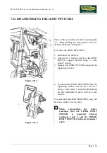
Page 115: ...SWITCH support bracket using a 3 mm Allen T wrench 3 Remove the LIMIT SWITCH group and the supporting bracket Figure 7 21 2 4 To remove the LIMIT SWITCHES from the supporting bracket unscrew the 2 scr...

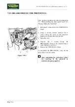
Page 116: ...the PHOTOCELL board 2 Using a 10 mm wrench unscrew the 2 screws fixing the cover of the protective housing of encoder wheel b if present 3 Open the cover 4 Unscrew the 2 screws fixing the PHOTOCELL b...

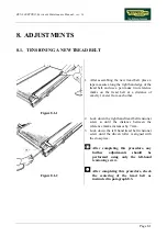
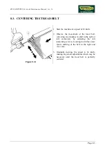
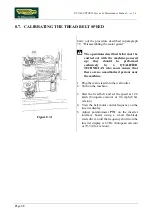
Page 117: ...exactly 1 meter from each other Figure 8 1 2 2 Lock down the right hand tread belt tensioner screw a until the distance between the reference marks increases by 7 mm 3 Lock down the left hand tread b...

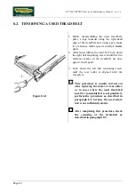
Page 118: ...ng screw a until the two reference marks on the tread belt are once again 1 meter apart 3 Lock down the left belt tensioning screw until the rear roller is aligned with the crosspiece This procedure i...

Page 119: ...he movement of the tread belt correcting any tendency to shift to the right or left exclusively by adjusting the left tensioning screw a Locking down this screw favors shifting of the belt to the righ...

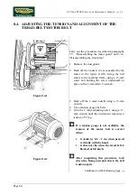
Page 120: ...a 13 mm screw and holding the screw underneath in place with a 6 mm Allen T wrench Figure 8 4 2 3 Back off the 2 outer nuts b using a 13 mm wrench 4 Use a tension gauge for belts 5 Turn the 2 inner ad...

Page 121: ...reference rod d rested against the driving roller pulley and make sure that The pulley and flywheel are parallel 1 Repeat steps 3 and 4 2 Make the adjustment by turning the 2 inner adjuster nuts c us...

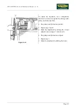
Page 122: ...hine on its maximum elevation position 2 Remove the belt guard The elevation motor belt tension is correct when it has a play of approximately 1 5 cm at the point A indicated by the arrow Figure 8 5 2...

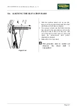
Page 123: ...wheel shaft holes on both bars are aligned 2 Use a gauge to make sure that both elevation bars project by the same distance A from the lead screw nuts If this is not the case turn one of the bars by h...

Page 124: ...QUALIFIED TECHNICIAN who must ensure that there are no unauthorized persons near the machine 1 Plug the mains lead into the wall outlet 2 Turn on the machine 3 Start the tread belt and set the speed...

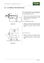
Page 125: ...the 2 fixing screws of the cover of the protective housing of the encoder wheel where present 2 Open the cover For the BONFIGLIOLI motor 3 Adjust the centering of the encoder photocell by turning the...

Page 126: ...RUN 600 XTPRO Service Maintenance Manual rev 1 3 Page 8 10 Page intentionally left blank...

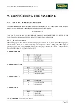
Page 127: ...e actual settings 9 1 1 LANGUAGE USED When a language is chosen from the list of languages available all the messages on the display are automatically shown in the chosen language To change the curren...

Page 128: ...input the desired time using the numeric keys and press ENTER to confirm 9 1 4 ACTIVATING THE AND KEYS The user can enable the and keys to modify the target heart rate during exercise sessions in CPR...

Page 129: ...a signal available from only one of the 2 sources it will be used even if it has not been configured as the priority source To change this setting when the LED display is showing the current priority...

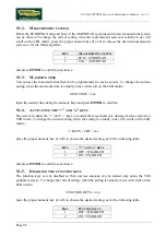
Page 130: ...enable or disable the scrolling function as shown in the table below KEY DISPLAY MODE 1 OFF DISABLED 2 ON ENABLED then press ENTER to confirm the choice The system will now go back to the standby mode...

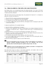
Page 131: ...maintenance information at the desired values for example after replacing the CPU board with the equipment in the standby mode press number keys 314 at the same time The following message will appear...

Page 132: ...he desired value using the numeric keys to enter and press ENTER to confirm Just press ENTER to maintain the original value 9 4 4 DISTANCE COVERED To change this value when the value actually in memor...

Page 133: ...without saving press the FUNC key After this the display will revert to showing the selected main function To display the extended function parameters 1 Press the 1 or 2 keys to display the desired f...

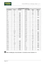
Page 134: ...82 Selection of voltage of AVR function for the motor 240 b12 Level of electronic thermal setting 8 00 b22 Level of overload restriction setting 12 00 b83 Carrier frequency setting KHz 16 0 b90 Dynami...

Page 135: ...ns that the type C extended functions are available 10 Press the FUNC key to access the extended function the display will show A 0 11 Press the 1 key once to view the value of the parameter the displ...

Page 136: ...A 13 0 YES A 55 0 YES A 14 0 YES A 56 1 YES A 15 0 YES A 57 0 YES A 16 0 YES A 58 1 YES A 17 0 YES A 62 50 YES A 18 10 0 YES A 63 98 A 19 10 0 YES A 64 0 YES A 20 0 5 YES A 68 0 5 YES A 21 0 YES A 71...

Page 137: ...t once a week For external cleaning proceeds as follows 10 1 1 SETTING UP THE OPERATION 1 Turn off the machine by placing the switch in the 0 position OFF 2 Unplug the mains lead from the wall outlet...

Page 138: ...d clean it using compressed air or a vacuum cleaner 6 Move the machine and clean the floor underneath using a vacuum cleaner 10 2 2 LUBRICATING THE ELEVATION BARS Carry out these operations approximat...

Page 139: ...Technical Service or adjust the tension 2 With the machine moving at a speed of approximately 10 km h 7 mph check the centering of the tread belt If any anomalies are found call in the authorized Tech...

Page 140: ...ORKING CONDITIONS 1 Check that the special plate is present under the machine wheels 2 Check that the machine is connected directly to the wall outlet without any extension cords and that the outlet i...

Page 141: ...lead from the wall outlet 4 Remove the guard plate of the elevation motor drive belt 5 Check the state of wear of the elevation motor drive belt Replace if it shows evident signs of wear 6 Check the t...

Page 142: ...sing a heart rate frequency simulator check that the machine does not detect its presence and doesn t alter the previously measured heart rate 10 3 13 CHECKING THE OPERATION OF THE HAND SENSOR RECEIVE...

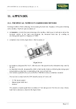
Page 143: ...eiver shown in the figure below which consists of Figure 11 1 1 an antenna a designated the coil which receives the signal from the transmitter strap worn by the user an integrated circuit b designate...

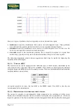
Page 144: ...which may be useful for improving the reception of the cardio signal 11 1 1 TYPE OF ASIC The cardio receivers can be equipped with 3 different types of ASIC models identifiable by the code marked on t...

Page 145: ...way it is possible to determine whether there is electromagnetic noise and identify its source The only effective solution in the presence of electromagnetic interference is to reduce the power of th...

Page 146: ...to the parallel combination of the added resistor and the existing 15 KOhm resistor 11 1 4 MECHANICAL VIBRATIONS Mechanical vibrations may cause slight shifting of the coil giving rise to transient im...

Page 147: ...ease note that even small departures from the above specifications may considerably impair the accuracy of reception The optimal configuration is therefore that shown in the figures below receiver hou...

Page 148: ...XTPRO Service Maintenance Manual rev 1 3 Page 11 6 Figure 11 1 4 11 1 6 ROUTING OF CABLES Particular care must be taken in the routing of cables to prevent interference with the receiver coil Figure...

Page 149: ...es into a given floor space area This technology is an evolution of the Polar Coded technology with which it is fully compatible The PCD system differs from Polar s standard coded technology because i...

Page 150: ...chine receives the user s heart rate signal but does not operate in coded mode Synchronization time 10 15 seconds maximum If the machines are installed extremely close together there may be interferen...

Page 151: ...y which stores the working program the output is disconnected E08 Low voltage protection A drop in the input voltage below 150 160 V triggers this error and the output is disconnected E09 CT error Whe...

Page 152: ...ing of the machine 11 4 PROCEDURE FOR CLEARING THE ERROR MEMORY ON HITACHI SJ100 INVERTER For all Hitachi SJ100 inverters it is available an easy procedure for clearing the error memory To do this 1 T...

Page 153: ...ress also Stop Reset key for about 1 second and wait for about 3 seconds until the blinking d00 is shown on the display 6 Now release all keys again The initializing phase that now begins will be comp...

Page 154: ...disconnected E7 EEPROM error When an error is detected on the EEPROM memory which stores the working program the output is disconnected E8 Low voltage protection A drop in the input voltage below 150...

Page 155: ...Be very careful not to touch any other keys or touch the aforesaid keys at the wrong time as this can seriously damage the inverter programming with consequent malfunctioning of the machine 11 7 PROCE...

Page 156: ...RUN 600 XTPRO Service Maintenance Manual rev 1 3 Page 11 14 Page intentionally left blank...

Page 157: ......

Page 158: ...0SM00080 ING TECHNOGYM S p A Via G Perticari 20 47035 Gambettola FC ITALIA Tel 39 0547 650438 Fax 39 0547 650150 e mail service technogym com...

Reviews: