RUNRACE : Service & Maintenance Manual - rev. 2.0
Page 7.24
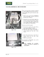
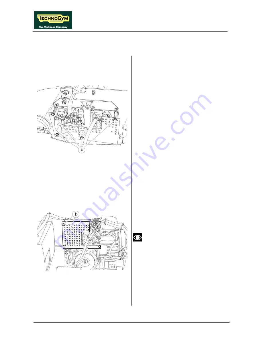
7.19. DISASSEMBLING THE ELECTRONIC CIRCUIT BOARDS
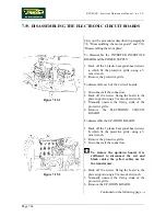
Figure 7.19-1
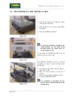
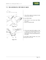
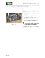
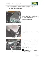
Carry out the procedures described in paragraphs
7.8. “Disassembling the motor guard” and 7.10.
“Disassembling the front plate”.
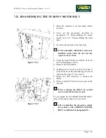
To disassemble the INVERTER INTERFACE
BOARD and the POWER SUPPLY:
1. Back off the 4 plastic hexagonal-head screws
a
which fix the protective grille, using a 7-
mm wrench.
2. Remove the protective grille.
To disassemble each of the 2 circuit boards:
3. Disconnect all the connectors.
4. Back off the screws fixing the board to the
plate support using a 7-mm socket wrench.
5. Manually unscrew the fixing studs of the
protective grille.
6. Remove the ELECTRONIC CIRCUIT
BOARD.
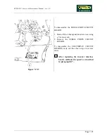
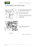
Figure 7.19-2
To disassemble the UP-DOWN BOARD:
1. Back off the 3 plastic hexagonal-head screws
b
which fix the protective grille, using a 7-
mm wrench.
2. Remove the protective grille.
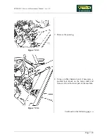
3. Disconnect all the connectors.
To remove the up-down board, it is
sufficient to disconnect the red and
black cables; the yellow cables are for
the transformer.
4. Back off the screws fixing the board to the
plate support using a 7-mm socket wrench.
5. Manually unscrew the fixing studs of the
protective grille.
6. Remove the UP-DOWN BOARD.
Continued on the following page
→
Summary of Contents for Runrace
Page 1: ...SERVICE MAINTENANCE MANUAL REV 2 0 ...
Page 2: ......
Page 4: ......
Page 28: ...RUNRACE Service Maintenance Manual rev 2 0 Page 2 18 Page intentionally left blank ...
Page 144: ...RUNRACE Service Maintenance Manual rev 2 0 Page 8 12 Page intentionally left blank ...
Page 160: ...RUNRACE Service Maintenance Manual rev 2 0 Page 9 16 Page intentionally left blank ...
Page 182: ...RUNRACE Service Maintenance Manual rev 2 0 Page 11 16 Page intentionally left blank ...
Page 183: ......

