RUNRACE : Service & Maintenance Manual - rev. 2.0
Page 2.4
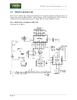
W
IRING
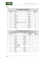
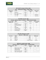
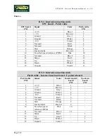
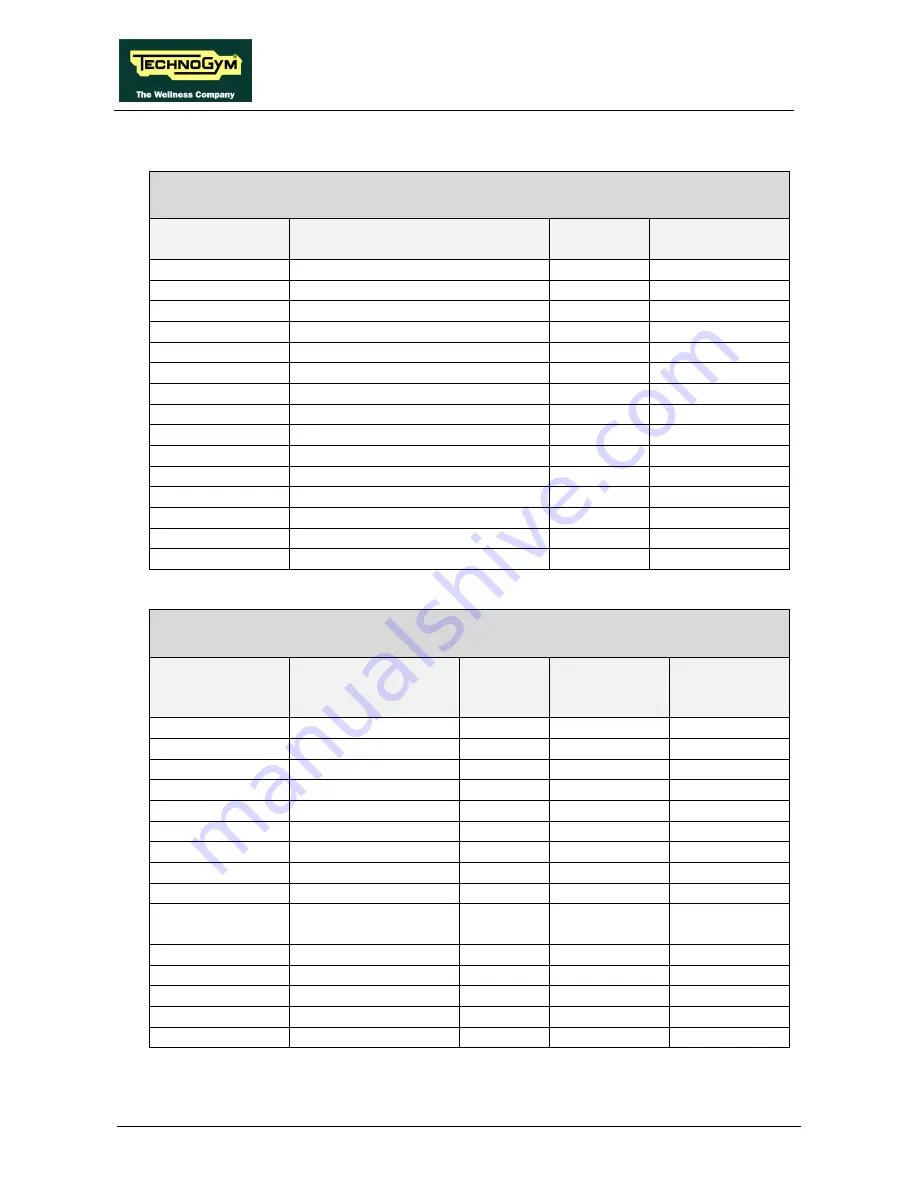
RN-1: Internal connection cable
CPU board – Patch cable
CPU board
CN1
Signal
Color
Patch cable
CN1
1
+12 V
Blue 1
1
2
+ 5 V
Brown 1
2
3 Ground
Gray
1
3
4 Ground
White
1 4
5
-12 V
Violet 1
5
6
Not used
Red 1
6
7 Not
used
Black
7
8 Start
Orange
8
9
Inverter alarm
Brown 2
9
10
Tread belt speed reference (PWM)
Pink
10
11
Not used
Blue 2
11
12 Status
Red
2
12
13 Up
Gray
2
13
14 Down
White
2 14
15 Ground
Violet
2 15
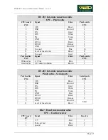
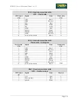
RN-2: Internal connection cable
Patch cable - Inverter interface board - Up-down board
Patch cable
CN2
Signal
Color
Inverter interf.
board
CN2
Up-down
board
CN2
1
+12 V
Blue 1
1
-
2
+ 5 V
Brown 1
2
-
3 Ground
Gray
1 3
-
4 Ground
White
1 4
-
5
-12 V
Violet 1
5
-
6
Not used
Red 1
6
-
7 Not
used
Black 7
-
8 Start
Orange 8
-
9
Inverter alarm
Brown 2
9
-
10
Tread belt speed
reference (PWM)
Pink 10
-
11
Not used
Blue 2
11
-
12 Status
Red
2 -
1
13 Up
Gray
2 -
2
14 Down
White
2 -
3
15 Ground
Violet
2 -
4
Summary of Contents for Runrace
Page 1: ...SERVICE MAINTENANCE MANUAL REV 2 0 ...
Page 2: ......
Page 4: ......
Page 28: ...RUNRACE Service Maintenance Manual rev 2 0 Page 2 18 Page intentionally left blank ...
Page 144: ...RUNRACE Service Maintenance Manual rev 2 0 Page 8 12 Page intentionally left blank ...
Page 160: ...RUNRACE Service Maintenance Manual rev 2 0 Page 9 16 Page intentionally left blank ...
Page 182: ...RUNRACE Service Maintenance Manual rev 2 0 Page 11 16 Page intentionally left blank ...
Page 183: ......


