RUNRACE : Service & Maintenance Manual - rev. 2.0
Page 2.13
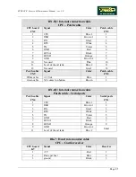
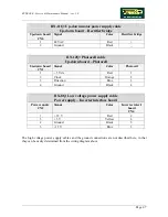
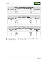
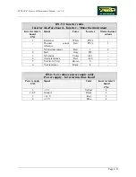
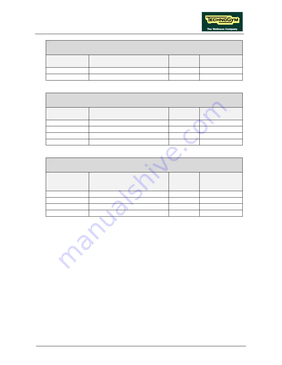
RN-11: Up-down motor power supply cable
Up-down board – Rectifier bridge
Up-down board
CN6
Signal
Color
Rectifier bridge
1 48
VAC
Red
+
2 Ground
Black
−
RN-12: Photocell cable
Up-down board – Photocell
Up-down board
CN1
Signal
Color
Photocell
1
+ 5 Vdc
Red
1
2 Clock
Orange
2
3 Direction
Blue
3
4 ground
Black
4
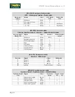
RX-8Q: Low voltage power supply cable
Power supply – Inverter interface board
Power supply
CN2
Signal
Color
Inverter interf.
board
CN4
3
+ 5 V
Yellow
4
4 Ground
Black
3
1
+ 12 V
Red
2
6
- 12 V
Blue
1
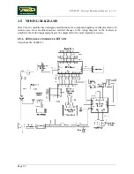
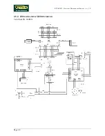
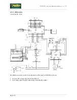
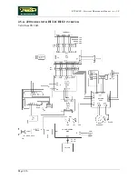
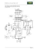
The high voltage power supply cables and the ground connections are not described here, in that
they can be easily determined from the wiring diagram above.
Summary of Contents for Runrace
Page 1: ...SERVICE MAINTENANCE MANUAL REV 2 0 ...
Page 2: ......
Page 4: ......
Page 28: ...RUNRACE Service Maintenance Manual rev 2 0 Page 2 18 Page intentionally left blank ...
Page 144: ...RUNRACE Service Maintenance Manual rev 2 0 Page 8 12 Page intentionally left blank ...
Page 160: ...RUNRACE Service Maintenance Manual rev 2 0 Page 9 16 Page intentionally left blank ...
Page 182: ...RUNRACE Service Maintenance Manual rev 2 0 Page 11 16 Page intentionally left blank ...
Page 183: ......

