RUNRACE : Service & Maintenance Manual - rev. 2.0
Page 3.3
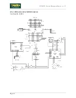
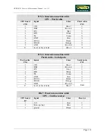
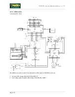
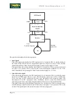
Regardless of whether the Lenze or Hitachi model is used, the inverter and interface board group
has the function of driving the tread belt motor at the desired speed, in accordance with the data
programmed on the machine CPU board and on the basis of the program saved on the inverter itself.
The inverter has a power of 2.2 KW.
3.1.5. I
NVERTER INTERFACE BOARD
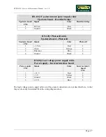
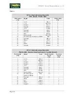
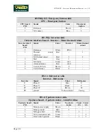
Receives from the display a PWM signal proportional to the selected speed, and converts it into a
continuous voltage for controlling the inverter. Receives the error signal generated by the inverter in
the event of problems and transmits it to the display. Receives the low voltages output by the power
supply and passes them to the display. There are 2 LEDs on the board:
•
DL1 illuminates when the tread belt is moving;
•
DL2 illuminates when the inverter does not detect any error conditions and therefore the alarm
signal is inactive.
3.1.6. B
ELT MOTOR
An asynchronous three-phase motor which, by means of a pulley and a poly-v belt, turns the driving
roller of the tread belt. Each motor phase is equipped with a normally-closed bimetallic safety which
opens when the temperature exceeds a preset threshold, in order to safeguard the integrity of the
motor. The 3 bimetallic safeties are connected in series and reach the inverter as a NC external input
signal. When this contact opens, the inverter generates an alarm.
The tread belt motor has a power of 2.2 KW (3 Hp).
3.1.7. U
P
-
DOWN MOTOR
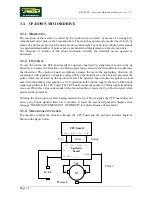
It is a DC motor (48 Vdc – 5 A) which, by means of a mechanical reduction unit and a timing belt,
turns the lead screw nuts on the threaded elevation bars, causing the machine to be raised or lowered
depending on the direction of rotation.
3.1.8. P
HOTOCELL
This is the device which provides feedback on the motion of the up-down motor. It transmits one
pulse for each tooth detected on the encoder wheel which is fixed to the gearmotor, and a signal
indicating the direction of movement.
Two different types of photocells are used on these machines:
•
Old model
: Siemens SFH910 photocell mounted on circuit board
GF92015-B
;
•
New model
: Optek OPB610 photocell mounted on circuit board
GF970711
.
The 2 photocells are mechanically interchangeable but functionally distinct — each one requires its
own specific SW version on the up-down board.
3.1.9. U
P
-
DOWN BOARD
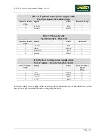
Receives from the display the enable signal for elevation motion and converts it into a control for
the up-down motor. Generates its power supply and the DC power supply for the motor by means of
Summary of Contents for Runrace
Page 1: ...SERVICE MAINTENANCE MANUAL REV 2 0 ...
Page 2: ......
Page 4: ......
Page 28: ...RUNRACE Service Maintenance Manual rev 2 0 Page 2 18 Page intentionally left blank ...
Page 144: ...RUNRACE Service Maintenance Manual rev 2 0 Page 8 12 Page intentionally left blank ...
Page 160: ...RUNRACE Service Maintenance Manual rev 2 0 Page 9 16 Page intentionally left blank ...
Page 182: ...RUNRACE Service Maintenance Manual rev 2 0 Page 11 16 Page intentionally left blank ...
Page 183: ......

