RUNRACE : Service & Maintenance Manual - rev. 2.0
Page 3.4
a transformer and rectifier bridge. Determines the motor position, and hence the treadmill elevation,
by means of the photocell. Generates and sends to the display a motion status signal at every 0.5%
variation in the elevation.
It is necessary to use the appropriate SW version for the photocell model, as identified by the label
on the chip:
•
Old
photocell model: chip version
M3S10
;
•
New
photocell model: chip version
RR52V2
.
It checks the lower and upper travel limits by means of 2 limit switches. The board includes 2 LEDs
associated to the limit switches, which are normally illuminated:
•
DL1
: comes off when the upper limit switch is tripped;
•
DL2
: on SMD board / DL3 on traditional board: comes off if the lower limit switch is tripped.
3.1.10. M
ICROSWITCHES
There are 2 limit switches which control the range of motion of the elevation mechanism. These
switches are positioned at the travel limits of the elevation bars, and change state when pressed
and/or released. The lower limit switch is NC, while the upper one is NO.
3.1.11. P
OWER SUPPLY
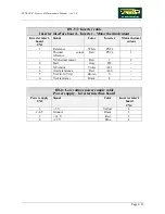
Receives the mains voltage at its input and outputs the DC voltages (+5 V, +12 V and
−
12 V) which
supply the display and the inverter interface board.
The model actually used is the Lambda SWT 40. This model has been starting used when the new
Hitachi SJ100 inverter has been used. The previous model used was the Lambda ZT 30.
3.1.12. S
ERIAL PORTS
These are ports which enable the machine to communicate with the outside world. Three such
interfaces are provided:
•
PRINTER
: RS-232 port for connecting the machine to a printer or other external device, such
as an ECG or metabolic monitor;
•
IN
: RS-485 input port, not used;
•
OUT
: RS-485 output port, not used.
3.1.13. E
MERGENCY BUTTON
This is the user safety device. Starting from the machine with SN 03000131, it consists of a new
maintained button which needs to be released after it has been pressed.
The button, which has a NC contact, is connected both to the CPU board and to a relay which
enables the inverter power supply. Once the button has been pressed, the relay shuts off the power
supply to the inverter and the motor stops. At the same time, the CPU board also detects that the
button was pressed, interrupts the exercise and shows a message on the display. To resume using the
machine, it is necessary to wait at least 5-10 seconds before returning the emergency button to the
working position.
Summary of Contents for Runrace
Page 1: ...SERVICE MAINTENANCE MANUAL REV 2 0 ...
Page 2: ......
Page 4: ......
Page 28: ...RUNRACE Service Maintenance Manual rev 2 0 Page 2 18 Page intentionally left blank ...
Page 144: ...RUNRACE Service Maintenance Manual rev 2 0 Page 8 12 Page intentionally left blank ...
Page 160: ...RUNRACE Service Maintenance Manual rev 2 0 Page 9 16 Page intentionally left blank ...
Page 182: ...RUNRACE Service Maintenance Manual rev 2 0 Page 11 16 Page intentionally left blank ...
Page 183: ......

