RUNRACE : Service & Maintenance Manual - rev. 2.0
Page 3.6
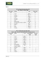
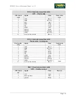
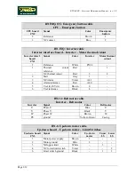
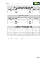
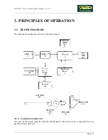
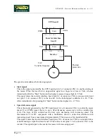
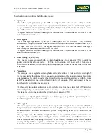
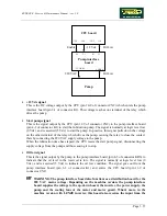
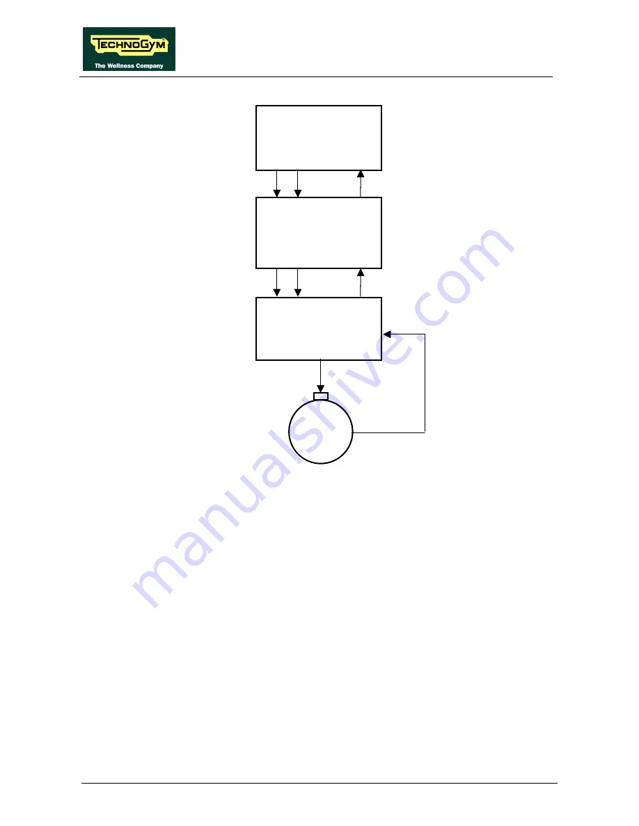
The speed control utilizes the following signals:
•
Start signal
This is the signal generated by the CPU board (pin 8-3 of connector CN1) to enable starting of
the motor. When the tread belt is stopped this signal is at logic level low (0 Vdc), whereas
immediately after the “Start” button on the display is pressed it goes high (4.5 Vdc).
The signal enters the inverter interface board (pin 8-3 of connector CN2), is processed and sent
out (pin 2-1 of connector CN1) to the inverter. In the belt-stopped condition it is -24.7 Vdc,
while immediately after pressing the “Start” button on the display it is -2.7 Vdc.
•
Speed reference signal
This is the signal generated by the CPU board (pins 10-3 of connector CN1) to control the motor
speed. It is a PWM signal, that is to say a fixed frequency square wave with a variable duty
cycle. The logic of this control has the duty cycle decreasing with increasing speed. The
measurement of its DC component with a multimeter shows a value that decreases with
increasing speed, from a maximum of approximately 5 Vdc down to a few hundred mVdc.
This signal enters the inverter interface board (pins 10-3 of connector CN2), is converted into a
variable analogue signal between 0 and 10 Vdc and sent out (pins 5-6 of connector CN1) to the
inverter. The signal input to the inverter increases with increasing speed.
CPU board
Inverter interface
board
Inverter
Alarm
Alarm
Start
Start
PWM
Vref
10-3 8-3
9-3
CN1
10-3
8-3
9-3
CN2
5-6
2-1
3-4
O-L 1-PV24
AL1-AL0
CN1
U-V-W
M
Thermal
protection
3-PV24
VAC
Variable frequency
Summary of Contents for Runrace
Page 1: ...SERVICE MAINTENANCE MANUAL REV 2 0 ...
Page 2: ......
Page 4: ......
Page 28: ...RUNRACE Service Maintenance Manual rev 2 0 Page 2 18 Page intentionally left blank ...
Page 144: ...RUNRACE Service Maintenance Manual rev 2 0 Page 8 12 Page intentionally left blank ...
Page 160: ...RUNRACE Service Maintenance Manual rev 2 0 Page 9 16 Page intentionally left blank ...
Page 182: ...RUNRACE Service Maintenance Manual rev 2 0 Page 11 16 Page intentionally left blank ...
Page 183: ......

