RUNRACE : Service & Maintenance Manual - rev. 2.0
Page i
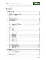
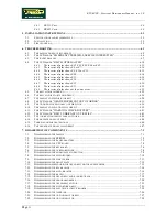
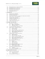
Contents
1.
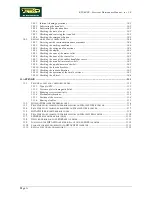
GENERAL NOTICES............................................................................................................................................1.1
1.1. I
NTRODUCTION
............................................................................................................................................ 1.1
1.2. R
ECOMMENDATIONS
................................................................................................................................... 1.1
1.3. G
ENERAL RULES FOR REPAIR PROCEDURES
................................................................................................. 1.2
2.
TECHNICAL CHARACTERISTICS ..................................................................................................................2.1
2.1. M
ECHANICAL CHARACTERISTICS
................................................................................................................. 2.1
2.2. E
LECTRICAL CHARACTERISTICS
................................................................................................................... 2.1
2.3. A
MBIENT SPECIFICATIONS
........................................................................................................................... 2.1
2.4. C
ONFORMITY TO REGULATIONS
................................................................................................................... 2.1
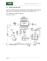
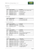
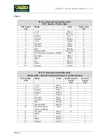
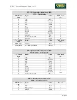
2.5. W
IRING DIAGRAMS
...................................................................................................................................... 2.2
2.5.1.
220 model co
nform
to IEC 601..........................................................................................
...
........2.2
2.5.2.
220 model with SJ100 inverter.....................................................................................................2.8
2.5.3.
220 model...................................................................................................................................2.14
2.5.4.
220 model with HITACHI E2 inverter........................................................................................2.16
2.5.5.
220 model with LENZE inverter.................................................................................................2.17
3.
PRINCIPLES OF OPERATION ..........................................................................................................................3.1
3.1. B
LOCK DIAGRAM
......................................................................................................................................... 3.1
3.1.1.
Cardio transmitter........................................................................................................................3.1
3.1.2.
Cardio receiver ............................................................................................................................3.2
3.1.3.
Display .........................................................................................................................................3.2
3.1.4.
Inverter.........................................................................................................................................3.2
3.1.5.
Inverter interface board ...............................................................................................................3.3
3.1.6.
Belt motor.....................................................................................................................................3.3
3.1.7.
Up-down motor ............................................................................................................................3.3
3.1.8.
Photocell ......................................................................................................................................3.3
3.1.9.
Up-down board ............................................................................................................................3.3
3.1.10.
Microswitches...............................................................................................................................3.4
3.1.11.
Power supply................................................................................................................................3.4
3.1.12.
Serial ports ...................................................................................................................................3.4
3.1.13.
Emergency button.........................................................................................................................3.4
3.2. T
READ
-
BELT MOTOR DRIVE
......................................................................................................................... 3.5
3.2.1.
Mechanics ....................................................................................................................................3.5
3.2.2.
Controls........................................................................................................................................3.5
3.2.3.
The signals involved .....................................................................................................................3.5
3.3. U
P
-
DOWN MOTOR DRIVE
............................................................................................................................. 3.8
3.3.1.
Mechanics ....................................................................................................................................3.8
3.3.2.
Controls........................................................................................................................................3.8
3.3.3.
The signals involved .....................................................................................................................3.8
3.4. A
UTOMATIC LUBRICATION SYSTEM
........................................................................................................... 3.11
3.4.1.
Mechanical components.............................................................................................................3.11
3.4.2.
Control signals ...........................................................................................................................3.11
3.4.3.
The signals .................................................................................................................................3.12
4.
ACCESSORIES......................................................................................................................................................4.1
4.1. C
ONNECTING TO THE TGS
............................................................................................................................ 4.1
4.1.1.
Non TGS-adapted machines.........................................................................................................4.1
4.1.2.
TGS-adapted machines ................................................................................................................4.1
4.2. C
ONNECTING TO THE PRINTER
..................................................................................................................... 4.2
4.3. C
ONNECTING TO AN EXTERNAL DEVICE
(ECG
AND
/
OR METABOLIC MONITOR
) ........................................... 4.3
4.4. PIN
OUT SERIAL PORTS
............................................................................................................................... 4.4
Summary of Contents for Runrace
Page 1: ...SERVICE MAINTENANCE MANUAL REV 2 0 ...
Page 2: ......
Page 4: ......
Page 28: ...RUNRACE Service Maintenance Manual rev 2 0 Page 2 18 Page intentionally left blank ...
Page 144: ...RUNRACE Service Maintenance Manual rev 2 0 Page 8 12 Page intentionally left blank ...
Page 160: ...RUNRACE Service Maintenance Manual rev 2 0 Page 9 16 Page intentionally left blank ...
Page 182: ...RUNRACE Service Maintenance Manual rev 2 0 Page 11 16 Page intentionally left blank ...
Page 183: ......


