RUNRACE : Service & Maintenance Manual - rev. 2.0
Page 6.13
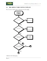
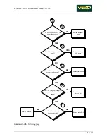
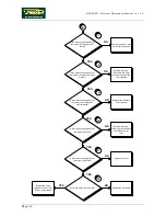
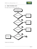
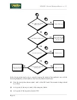
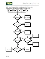
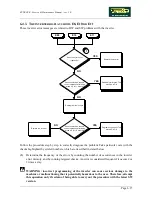
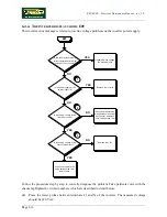
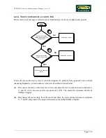
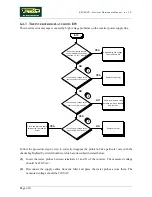
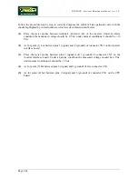
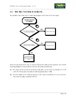
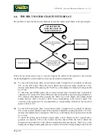
Follow the procedure step by step to correctly diagnose the problem. Take particular care with the
checks highlighted by circled numbers, which are described in detail below:
(1)
Disconnect the motor cable from the inverter and place the tester probes between its terminals
U-V, U-W and V-W. The measured resistance should be very high, in the order of MOhms. It
is difficult to obtain a stable resistance measurement, however, a phase can be considered
short-circuited or defective when the measured resistance is in the order of a few tens of
Ohms.
(2)
Place the tester probes between the blue - black, blue - brown and black - brown wires of the
motor cable. The measured resistance should be approximately 1.7 Ohm.
(3)
Disconnect the motor cable from the motor and place a tester between its terminals U-V, U-W
and V-W. The measured resistance should be 1.7 Ohm.
Summary of Contents for Runrace
Page 1: ...SERVICE MAINTENANCE MANUAL REV 2 0 ...
Page 2: ......
Page 4: ......
Page 28: ...RUNRACE Service Maintenance Manual rev 2 0 Page 2 18 Page intentionally left blank ...
Page 144: ...RUNRACE Service Maintenance Manual rev 2 0 Page 8 12 Page intentionally left blank ...
Page 160: ...RUNRACE Service Maintenance Manual rev 2 0 Page 9 16 Page intentionally left blank ...
Page 182: ...RUNRACE Service Maintenance Manual rev 2 0 Page 11 16 Page intentionally left blank ...
Page 183: ......

