STEPRACE: Service & Maintenance Manual - rev. 1.2
Page 3.6
•
Excitation signal (PWM)
This is the signal generated by the CPU board (pin 6-3 of connector CN1) for controlling the
resistance. It is a PWM signal, i.e. a fixed frequency square wave signal with variable duty
cycle. The logic of this control causes the duty cycle to increase with increasing resistance.
Measuring the dc component of this signal with a multimeter shows a value which increases
with increasing resistance, from a minimum of a few hundred mVdc to approximately 5 Vdc.
This signal enters the alternator interface board (pin 6-3 of connector CN1), and is sent to the
alternator (pin 4-5 of connector CN2 on the alternator interface board) to supply its rotor via the
brushes.
•
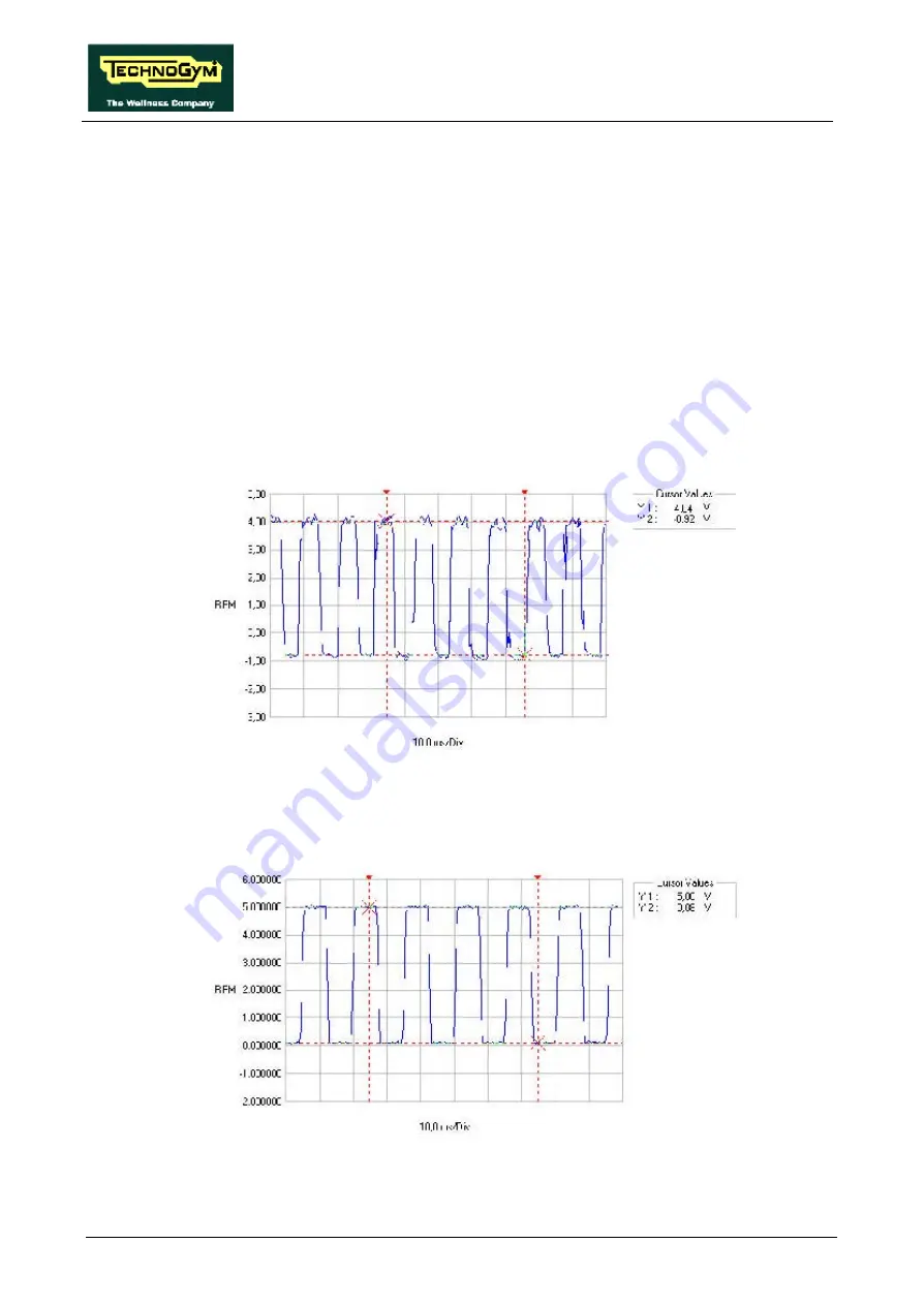
RPM Signal
This is the speed signal output by the alternator. It enters the alternator interface board (pin 1-5
of connector CN2) and is a square wave which varies from –1 Vdc to a maximum value
dependent on the training speed, as illustrated in the figure below:
The signal is cleaned and level-converted before being sent from the alternator interface board
(pins 5-3 of connector CN1) to the CPU board (pins 5-3 of connector CN1) as a square wave
which varies between 0 and 5 Vdc, as illustrated in the figure below:
Summary of Contents for Steprace
Page 1: ...SERVICE MAINTENANCE MANUAL REV 1 2...
Page 2: ......
Page 4: ......
Page 8: ...STEPRACE Service Maintenance Manual rev 1 2 Page iv Page intentionally left blank...
Page 16: ...STEPRACE Service Maintenance Manual rev 1 2 Page 2 6 Page intentionally left blank...
Page 46: ...STEPRACE Service Maintenance Manual rev 1 2 Page 6 20 Page intentionally left blank...
Page 96: ...STEPRACE Service Maintenance Manual rev 1 2 Page 8 12 Page intentionally left blank...
Page 104: ...STEPRACE Service Maintenance Manual rev 1 2 Page 10 6 Page intentionally left blank...
Page 113: ......


