STEPRACE: Service & Maintenance Manual - rev. 1.2
Page 6.14
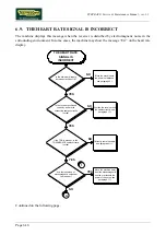
(2)
Place the tester probes on the microswitch terminals and check that, when the selection knob
is moved, the microswitch changes state from open to closed and vice versa.
The microswitch contact is NC for stepping mode A, and NO for stepping mode B.
(3)
Place the tester probes between pin 6 of connector CN2 on the alternator interface board and
the ground node, and check that moving the selection knob toggles the signal between 0 and 5
Vdc.
(4)
Place the tester probes between pins 8 and 3 of connector CN1 on the alternator interface
board, and check that moving the selection knob toggles the signal between 0 and 5 Vdc.
(5)
Place the tester probes between pins 8 and 3 of connector CN1 on the CPU board, and check
that moving the selection knob toggles the signal between 0 and 5 Vdc.
Summary of Contents for Steprace
Page 1: ...SERVICE MAINTENANCE MANUAL REV 1 2...
Page 2: ......
Page 4: ......
Page 8: ...STEPRACE Service Maintenance Manual rev 1 2 Page iv Page intentionally left blank...
Page 16: ...STEPRACE Service Maintenance Manual rev 1 2 Page 2 6 Page intentionally left blank...
Page 46: ...STEPRACE Service Maintenance Manual rev 1 2 Page 6 20 Page intentionally left blank...
Page 96: ...STEPRACE Service Maintenance Manual rev 1 2 Page 8 12 Page intentionally left blank...
Page 104: ...STEPRACE Service Maintenance Manual rev 1 2 Page 10 6 Page intentionally left blank...
Page 113: ......


