background image

 STEPRACE: Service & Maintenance Manual - rev. 1.2 


Page 7.17 

7.13.  DISASSEMBLING THE PEDAL CONNECTING RODS 


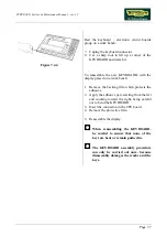
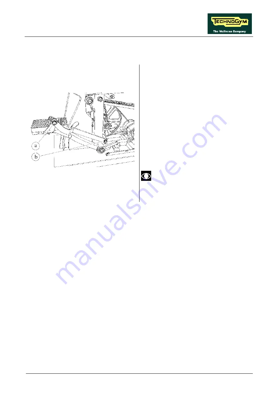
Figure 7.13-1 

 
Carry out the procedures described in paragraph 
7.8. “Disassembling the side guards”. 
 
Working from both sides: 
 
1.  Remove the protective cap 

a

2.  Back off the screw underneath the cap using 

a 17-mm wrench. 

3.  Back off screw 

b

 using a 17-mm wrench. 

4.  Remove the CONNECTING ROD. 
 
To reassemble the PEDAL CONNECTING 
RODS, carry out the above steps in reverse 
order. 
 

  Before reassembling the CONNECTING 

RODS, lubricate the bushings with a 
thin layer of chain grease. 


Summary of Contents for Steprace

Page 1: ...SERVICE MAINTENANCE MANUAL REV 1 2...

Page 2: ......

Page 3: ...EN THE MACHINE IS TURNED OFF NOTE The information contained in this document is subject to change without notice Technogym does not guarantee this documentation in any way Technogym shall not be held...

Page 4: ......

Page 5: ...TO THE PRINTER 4 2 5 INSTALLATION INSTRUCTIONS 5 1 5 1 SPECIFICATIONS AND REQUIREMENTS 5 1 5 2 INSTALLATION 5 1 5 3 FIRST POWER ON 5 2 6 TROUBLESHOOTING 6 1 6 1 THE DISPLAY DOES NOT ILLUMINATE 6 2 6...

Page 6: ...HE BELT 8 1 8 2 BELT TENSION 8 2 8 3 ALIGNING THE PRIMARY SHAFT SECONDARY SHAFT CHAIN 8 3 8 4 PRIMARY SHAFT SECONDARY SHAFT CHAIN TENSION 8 4 8 5 ADJUSTING THE ALIGNMENT OF THE PRIMARY DRIVE SPROCKET...

Page 7: ...the operation of the cardio receiver 10 4 10 3 13 Checking the resistance setting 10 5 10 3 14 Checking the noise of the brushes 10 5 11 APPENDIX 11 1 11 1 TECHNICAL NOTES ON CARDIO RECEIVERS 11 1 11...

Page 8: ...STEPRACE Service Maintenance Manual rev 1 2 Page iv Page intentionally left blank...

Page 9: ...n observance may cause damage to the machine Information about the operation in progress OBSERVE observation about the operation in progress 1 2 RECOMMENDATIONS Technogym recommends the following step...

Page 10: ...ecommended brands 3 Use special tools where specified 4 Consult the Technical Newsletters which may contain more up to date information on adjustments and maintenance than those contained in this manu...

Page 11: ...ircuit board An incorrect voltage setting can cause irreversible damage to the power supply unit Before changing the mains voltage setting the machine must be turned off and the mains lead unplugged f...

Page 12: ...ORS CPU board name type of connector connection CN1 AMP MATE N LOCK 12 pin F to alternator interface board CN3 AMP MODU II 4 pin M to cardio receiver Power supply name type of connector connection CN1...

Page 13: ...und Black 3 4 ground Orange 4 5 Alternator RPM X 6 Pink 5 6 PWM alternator resistance Red 6 7 7 8 Selection knob position Black Blue 8 9 CTS Blue 9 10 Master Slave selection Purple 10 11 Y bus Green 1...

Page 14: ...tation Orange Red Faston ST 5M Microswitch cable Microswitch Alternator interface board PE Microswitch Signal Color Alternator interface board CN2 PE 1 ground Brown 6 2 NC Yellow green Yellow eyelet 4...

Page 15: ...Page 2 5 ST 8 Serial ports cable Alternator interface board Serial ports Alternator interface board CN4 Signal Color Serial ports 1 Y bus White 1 2 Z bus Orange 2 3 A bus Brown 3 4 B bus Yellow 4 5 CT...

Page 16: ...STEPRACE Service Maintenance Manual rev 1 2 Page 2 6 Page intentionally left blank...

Page 17: ...IAGRAM The block diagram of the machine is shown in the figure below 1 CARDIO TRANSMITTER It is worn by the person using the machine and transmits to the cardio receiver one pulse for every heart beat...

Page 18: ...non coded and there are 2 transmitters within its area of reception it will receive signals from both and may produce an error or irregular reading 3 DISPLAY This is the heart of the machine which co...

Page 19: ...nd opens when the temperature exceeds an established threshold 7 POWER RESISTOR Has the function of dissipating the energy produced by the alternator 8 SELECTION KNOB This knob is used for selecting t...

Page 20: ...tor which generates a resistance to the movement that is proportional to the excitation level To do this the CPU board transmits a PWM Pulse Width Modulation signal to the alternator interface board w...

Page 21: ...y level of the workout by means of the CPU board the alternator interface board and the alternator as illustrated in the figure below The following signals are involved in the control loop Microswitch...

Page 22: ...ly 5 Vdc This signal enters the alternator interface board pin 6 3 of connector CN1 and is sent to the alternator pin 4 5 of connector CN2 on the alternator interface board to supply its rotor via the...

Page 23: ...n half duplex mode Install the special cable illustrated below to make this serial port available on a 9 pin D connector at the back of the display TGSRN2RACE Internal cable Retrofit support flange CP...

Page 24: ...er is connected using a special cable which can be ordered using code A419 This cable is equipped with an RS 485 to RS 232 serial converter The printer connection diagram is as follows WARNING In orde...

Page 25: ...recommended to connect only machines of the same type in cascade up to a maximum of 5 machines In this case make sure that the wall output has a power rating of at least 300 Watt 10 Position the main...

Page 26: ...LEDs At the end of the power on test the machine enters standby mode awaiting a keyboard command To check the correct operation of the machine start exercising check that the SPM value displayed vari...

Page 27: ...se This type of box is a step in the troubleshooting procedure where an ACTION must be carried out It typically contains a description of the ACTION necessary to resolve the problem Therefore after ex...

Page 28: ...the correct voltage Is the mains voltage present at the output of the power input socket Replace the blown fuses Replace the mains lead Connect machine to a suitable electrical output Replace the inp...

Page 29: ...ace cable ST 1 YES NO NO YES NO YES 4 5 6 Are DC voltages output by the power supply correct 3 Replace the power supply YES A Follow the procedure step by step to correctly diagnose the problem Take p...

Page 30: ...ctor CN2 on the power supply to access the pins with the tester probes Check that all the output voltages of the power supply are correct referring to paragraph 2 5 2 Wiring 4 As for step 3 but on con...

Page 31: ...ternator excitation circuit ok Execute the procedure The resistance is incorrect YES Is the alternator overheated NO Allow it to cool down and then try again The thermal cutout is probably tripped YES...

Page 32: ...ge output by the alternator interface board correct Is the power resistor value correct Replace the power resistor Check and or replace cable BX 5 YES NO YES NO NO YES 1 2 3 Does the alternator interf...

Page 33: ...in Table 6 3 1 the excitation voltage should vary as shown in the same table EXCITATION VOLTAGE Vdc PWM SIGNAL Vdc Alternator interface board LEVEL OF RESISTANCE Alternator 4 5 CN2 6 3 CN1 CPU board 6...

Page 34: ...STEPRACE Service Maintenance Manual rev 1 2 Page 6 8 5 As for step 5 but with the oscilloscope between pins 6 and 3 of connector CN1 of the display CPU board...

Page 35: ...s the SPM signal output correctly by the alternator Is the SPM signal on connector CN2 of the alternator interface board correct Is the SPM signal on connector CN1 of the alternator interface board co...

Page 36: ...obes of an oscilloscope between the violet wire and the alternator ground When the speed is varied the waveform frequency should vary as shown in the table below SPM FREQUENCY Hz 60 187 70 218 80 249...

Page 37: ...ectly Correctly configure the machine Replace or rewire the printer cable Replace the CPU board There is a problem with the printer or the PC serial port or their respective configurations YES NO YES...

Page 38: ...t the other end to the machine Choose any workout program as soon as the last value entered has been confirmed the workout starts and the machine immediately transmits the data via the serial port The...

Page 39: ...he microswitch Replace cable ST 5M THE MACHINE DOES NOT READ THE STATE OF THE MICROSWITCH Does the microswitch signal reach the output of the alternator interface board NO YES NO YES NO YES NO YES 4 R...

Page 40: ...ter probes between pin 6 of connector CN2 on the alternator interface board and the ground node and check that moving the selection knob toggles the signal between 0 and 5 Vdc 4 Place the tester probe...

Page 41: ...to the alternator interface board correct Does the relay on the alternator interface board switch when the Master Slave signal changes state Replace the CPU board Replace cable ST 1 Replace the altern...

Page 42: ...between pins 10 and 3 of connector CN1 on the alternator interface board and check that the reading is 5 Vdc when the machine is configured as master and 0 Vdc when the machine is configured as SLAVE...

Page 43: ...repair cable ST 7 Replace the display CPU board 1 2 YES NO YES NO Follow the procedure step by step to correctly diagnose the problem Take particular care with the checks highlighted by circled numbe...

Page 44: ...chines OK Is the receiver positioned correctly and are the connecting cables correctly routed If the TGS is present is the TGSRN2RACE cable correctly routed Are there sources of electromagnetic noise...

Page 45: ...ircled numbers which are described in detail below 1 To check for electromagnetic noise near the machine use a frequency signal monitor constructed as shown in the schematic below The circuit lights t...

Page 46: ...STEPRACE Service Maintenance Manual rev 1 2 Page 6 20 Page intentionally left blank...

Page 47: ...E DISPLAY Figure 7 1 1 1 Turn off the machine and unplug the mains lead from the wall outlet 2 Back off the 3 screws a using a 4 mm hex T wrench Figure 7 1 2 3 Back off the 2 screws b using a medium P...

Page 48: ...rvice Maintenance Manual rev 1 2 Page 7 2 Figure 7 1 3 4 Open the DISPLAY To remove the DISPLAY 1 Disconnect connector c 2 Remove the DISPLAY To reassemble the DISPLAY carry out the above steps in rev...

Page 49: ...r is fixed to the display with only 2 screws Figure 7 2 2 4 Remove the EPROM b from its socket using an IC extractor tool Figure 7 2 3 To reassemble the EPROM 1 Make sure that reference index c on the...

Page 50: ...rotective cover Figure 7 3 2 Carry out the procedures described in paragraph 7 1 Disassembling the display With the display placed on a work bench 4 Back off the 13 screws b using a small Philips scre...

Page 51: ...d h by flipping it over toward the left being careful not to damage cable strip i 10 Manually disconnect the cable strip i from the CPU board 11 Remove the circuit boards 12 To disconnect the LCD from...

Page 52: ...ective cover Figure 7 4 2 Carry out the procedures described in paragraph 7 1 Disassembling the display With the display placed on a work bench 4 Back off the 13 screws b using a small Philips screwdr...

Page 53: ...work bench 1 Remove the backing film which protects the adhesive 2 Apply the adhesive part starting from the left and working toward the right being careful not to bend the KEYBOARD 3 Insert the conn...

Page 54: ...a flat blade screwdriver to open the box a which contains the RECEIVER Figure 7 5 2 If the receiver is positioned inside the display 3 Use a flat blade screwdriver to detach the box b which contains t...

Page 55: ...D Figure 7 6 1 1 Turn off the machine and unplug the mains lead from the wall outlet 2 Back off the 4 fixing screws a on the UPRIGHT GUARD using a large Philips screwdriver Figure 7 6 2 3 Remove the U...

Page 56: ...ich fix the board to the plate support using a 7 mm socket wrench 5 Remove the circuit board To disassemble the ALTERNATOR INTERFACE BOARD c 1 Disconnect the 4 connectors CN1 CN2 CN3 and CN4 2 Back of...

Page 57: ...utlet 2 Select stepping mode B dependent stepping motion On either side of the machine 3 Back off the 5 fixing screws a of the SIDE GUARD using a large Philips screwdriver 4 Pull the SIDE GUARD upward...

Page 58: ...the ball joint using a 17 mm socket wrench 2 Lower the pedal to the ground 3 Repeat the same procedure on the left pedal Figure 7 9 2 4 On each side of the machine back off the 2 screws b using a 5 m...

Page 59: ...ling the upright guard For each SIDE HANDLEBAR 1 Back off the 2 screws a using a 17 mm wrench 2 Remove the HANDLEBAR The SIDE HANDLEBARS can be inverted For the CENTER HANDLEBAR 1 Disassemble the 2 SI...

Page 60: ...om the wall outlet 1 Select stepping mode B dependent stepping motion Working from both sides 2 Align the pedals 3 Raise one pedal and back off the screw a which fixes the PEDAL JOINT to the chain of...

Page 61: ...from both sides 2 Remove the protective cap a 3 Back off the screw underneath the cap using 17 mm wrench Figure 7 12 2 To disassemble the bracket 4 Back off the 4 nuts b which fix the bracket c to the...

Page 62: ...remove the PEDAL GROUP pivot from the lever 9 Remove the PEDAL GROUP To reassemble the PEDAL GROUPS carry out the above steps in reverse order Align the fixing hole of the PEDAL GROUP pivot with the...

Page 63: ...the side guards Working from both sides 1 Remove the protective cap a 2 Back off the screw underneath the cap using a 17 mm wrench 3 Back off screw b using a 17 mm wrench 4 Remove the CONNECTING ROD T...

Page 64: ...ing the pedal joint up until step 3 7 12 Disassembling the pedals and pedal group and 7 13 Disassembling the pedal connecting rods 1 Select training mode B dependent stepping motion On both sides of t...

Page 65: ...pping motion To disassemble the PEDAL CHAINS on both ends of the CHAIN 2 Release clip a from the link using the special pliers 3 Remove the connecting plate b 4 Remove the connecting link c 5 Remove t...

Page 66: ...ard 1 Turn the CHAIN until the connecting link a is on the sprocket wheel of primary shaft b 2 Release clip c from the link using the special pliers 3 Remove the connecting plate d 4 Remove the connec...

Page 67: ...frame using a 17 mm wrench 3 Remove the PRIMARY SHAFT Figure 7 17 2 To disassemble the components of the PRIMARY SHAFT rest the group on a work bench 1 Back off the 2 dowels b which fix the bearings...

Page 68: ...ards and 7 9 Disassembling the chain guard On each side of the machine 1 Back off the lock nut a using a 32 mm wrench 2 Lock down shaft b using an 8 mm hex T wrench 3 Remove shaft b pulling out the DR...

Page 69: ...pright guard On each side of the machine 1 Select stepping mode B dependent stepping motion 2 Back off dowel a using a 3 mm hex T wrench Figure 7 19 2 3 Using a pointed tool and a rubber mallet push t...

Page 70: ...20 1 Carry out the procedure described in paragraph 7 6 Disassembling the upright guard 1 Select stepping mode B dependent stepping motion 2 Back off screw a using a 22 mm wrench 3 Remove the SLIDE D...

Page 71: ...17 mm wrench Figure 7 21 2 4 Back off the dowel b using a 4 mm hex T wrench 5 Shift the alternator toward the pulley in order to slacken belt c Figure 7 21 3 6 From both sides of the machine back off...

Page 72: ...ce Maintenance Manual rev 1 2 Page 7 26 After completing the procedure adjust the alignment and tension of the belt and of the primary shaft secondary shaft chain as described in the paragraphs 8 1 8...

Page 73: ...from the alternator flywheel Figure 7 22 3 4 Remove the BELT d from the pulley on the side opposite the chain 5 Back off nut e and the secondary shaft adjusting screw f using a 13 mm wrench 6 Back off...

Page 74: ...1 2 Page 7 28 If the gap is not large enough for the BELT to pass through disassemble the primary shaft secondary shaft chain After completing the procedure adjust the alignment and tension of the bel...

Page 75: ...machine frame using a 17 mm wrench 4 Back off the dowel d using a 4 mm hex T wrench 5 Shift the ALTERNATOR until belt e can be removed 6 Back off the lock nut of the alternator pin f using a 19 mm wr...

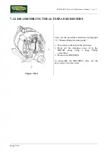
Page 76: ...24 1 Carry out the procedures described in paragraph 7 8 Disassembling the side guards 1 Disconnect cable a from the alternator 2 Back off the clamping screw b of the BRUSH group using a large Philip...

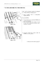
Page 77: ...pright guard 1 Select stepping mode A independent stepping motion For each SPRING 2 Using a hooked tool extend the SPRING and secure it to the frame 3 Back off self locking nut a using a 17 mm wrench...

Page 78: ...Manual rev 1 2 Page 7 32 Figure 7 25 3 5 Remove the SPRING from the upper pulley b 6 Using a pipe wrench unscrew the SPRING from the slide c 7 Remove the SPRING To reassemble the SPRINGS carry out the...

Page 79: ...s described in paragraph 7 25 Disassembling the springs leaving them connected to the slide For each PULLEY 1 Back off the self locking nut a using a 17 mm wrench while holding its screw b in place wi...

Page 80: ...rews a which fix the BARS to the frame using a 17 mm wrench 3 Remove the BARS and SLIDE Figure 7 27 2 To disassemble the runner from the SLIDE 1 Back off the 4 screws b using a 5 mm hex T wrench 2 Rem...

Page 81: ...e wall outlet 2 Back off the 2 dowels a using a 3 mm hex T wrench 3 Back off screw a using a 4 mm hex T wrench 4 Pull firmly to remove the KNOB from its pin To reassemble the KNOB carry out the above...

Page 82: ...ng the springs 7 27 Disassembling the slide bars and 7 28 Disassembling the selection knob 1 Select stepping mode A independent stepping motion 2 Back off the 2 screws a using a medium Philips screwdr...

Page 83: ...remove the pointed tool 6 Gradually reduce the pressure on the PIN until it can be removed from the front together with its spring To reassemble the SELECTION KNOB PIN carry out the above steps in re...

Page 84: ...lips screwdriver 4 Remove guard b by turning it through 90 and pulling it out toward the right Figure 7 30 2 5 Disconnect the 2 Fastons of the MICROSWITCH connecting cable 6 Back off the 2 screws c us...

Page 85: ...ing dowel c of alternator pivot b using a 4 mm hex T wrench 3 Placing a straight reference rod d against pulley f verify the alignment of belt e by checking that the reference rod d is parallel with b...

Page 86: ...ut of alternator pivot a using a 19 mm wrench 2 Back off the dowel b of the alternator pivot 3 Back off the nut c of the belt tension rod d using a 17 mm wrench 4 Rotate the alternator on its pivot in...

Page 87: ...crew a on sprocket b of the secondary shaft 2 Place a reference rod against the sprocket wheel of the primary shaft 3 Align the sprocket b of the secondary shaft with the reference rod 4 After complet...

Page 88: ...n at the point midway between the 2 shafts is approximately1 cm 3 Check the amount of vertical play at the midway point with the pedals in various different positions Check that the above adjustments...

Page 89: ...procedures described in paragraphs 7 8 Disassembling the side guards and 7 9 Disassembling the chain guard 1 Back off lock nut a using a 32 mm wrench 2 Adjust the position of shaft b using an 8 mm he...

Page 90: ...the side guards Inspect the 2 brushes for wear referring to the figures at left and to the descriptions below The brush shown in A has a correct wear pattern The brush shown in B has an irregular wear...

Page 91: ...st the position of the limit stop pad b for each PEDAL locking it down or backing it off so that The PEDALS are at the same height The PEDALS do not touch the machine guards 4 Select stepping mode B d...

Page 92: ...DE 4 Lightly lock down the 4 fixing screws a of the BARS 5 Select stepping mode A independent stepping motion 6 Move the SLIDE up and down along the BARS 7 Check that the slide is able to move freely...

Page 93: ...n knob pin for the guard only 1 Back off the MICROSWITCH fixing screws a and adjust its position so that in stepping mode A independent stepping motion its wheel does not touch the selection knob in s...

Page 94: ...8 10 1 After the machine has been switched on for at least 1 hour without switching it off 1 Adjust trimmer P1 on the back of the display to obtain the desired level of LCD luminosity This adjustment...

Page 95: ...anual rev 1 2 Page 8 11 8 11 ADJUSTING THE BUZZER TONE Figure 8 11 1 Turn on the machine and when the buzzer is sounded during the start up procedure 1 Adjust trimmer P2 on the back of the display to...

Page 96: ...STEPRACE Service Maintenance Manual rev 1 2 Page 8 12 Page intentionally left blank...

Page 97: ...FF OFF ON OFF 4 ON OFF ON OFF 5 To be enabled for printing the machine must be configured with all dip switches in ON position 9 1 2 ALTERNATOR CONFIGURATION This procedure is applicable starting from...

Page 98: ...ng the user if the microswitch is not present Left hand bank Dip switch 2 Microswitch ON Absent OFF Present In the case of TGS type SW the presence of the microswitch is configured by setting the posi...

Page 99: ...TERNAL CLEANING OPERATIONS These operations can be carried out by the owner of the machine and do not require any special skills The external cleaning operations are involve simple cleaning for the pu...

Page 100: ...uit boards WARNING when carrying out these operations be careful not to damage the cables 2 Move the machine and clean the floor underneath using a vacuum cleaner 10 2 3 LUBRICATION 1 Lubricate the pe...

Page 101: ...3 2 CHECKING THE WORKING CONDITIONS 1 Check that the machine is connected directly to the wall outlet without any extension cords and that the outlet is correctly earthed 2 If the machine is supplied...

Page 102: ...9 CHECKING THE PRIMARY SHAFT CHAIN 1 Check the state of wear of the primary shaft chain in particular checking for any links that are jammed and or have excessive play Replace if it shows evident sig...

Page 103: ...TING 1 Working in stepping mode A select the manual training program and check that when the difficulty level is changed the resistance of the machine varies accordingly 10 3 14 CHECKING THE NOISE OF...

Page 104: ...STEPRACE Service Maintenance Manual rev 1 2 Page 10 6 Page intentionally left blank...

Page 105: ...er shown in the figure below which consists of Figure 11 1 1 an antenna a designated the coil which receives the signal from the transmitter strap worn by the user an integrated circuit b designated t...

Page 106: ...ch may be useful for improving the reception of the cardio signal 11 1 1 TYPE OF ASIC The cardio receivers can be equipped with 3 different types of ASIC models identifiable by the code marked on the...

Page 107: ...ay it is possible to determine whether there is electromagnetic noise and identify its source The only effective solution in the presence of electromagnetic interference is to reduce the power of the...

Page 108: ...l combination of the added resistor and the existing 15 KOhm resistor 11 1 4 MECHANICAL VIBRATIONS Mechanical vibrations may cause slight shifting of the coil giving rise to transient impulses If thes...

Page 109: ...hown in the figure below Figure 11 1 2 Please note that even small departures from the above specifications may considerably impair the accuracy of reception The optimal configuration is therefore tha...

Page 110: ...of machines into a given floor space area This technology is an evolution of the Polar Coded technology with which it is fully compatible The PCD system differs from Polar s standard coded technology...

Page 111: ...erence problems in reading the user s heart rate signal as on traditional machines If the user wears a coded strap and trains on a machine equipped with a standard receiver if the machine is not using...

Page 112: ...sly press the 1 4 7 keys the LCD will show ALT 0 1 to indicate that the installed alternator model is a REAL MAGNETI MARELLI or EFEL either the new type 1 characterized by a red mark on the side oppos...

Page 113: ......

Page 114: ...0SMM0020 ING TECHNOGYM INDUSTRIE S r l Via G Perticari 20 47035 Gambettola FC ITALIA Tel 39 0547 56047 Fax 39 0547 650150 e mail service technogym com...

Reviews: